Showing posts with label light. Show all posts

Monday, November 17, 2014

Emergency Light 555

Emergency Lamp With 555 is one solution for lighting during power outages. With Emergency Lamp Series 555 uses a 12VDC voltage source that can be supplied from the 12V battery. Emergency Lamp 555 Series With these very simple and easy to make because all the components easily available in the market. Emergency Lamp Series With this 555 can turn on the light 5W-10W. The circuit is built with an astable multivibrator with the IC 555 that is used to mendrive transformer through Q1. For more details can be viewed directly from the series Emergency Lamp With 555 follows.

Emergency

Working frequency range of 555 Emergency Lamp With this set of configurations R1, R2 and C2. T1 in series Emergency Lamp With 10V 500mA 555 is a transformer. Secondary part (0-10V) is connected to the Q1 to be given the signal from the multivibrator. Then the primary (0-220V) is connected to the lamp.
Read More

Thursday, November 13, 2014

Fluorescent Light Wiring Diagram Tube Light Circuit

This post "Fluorescent Light Wiring Diagram | Tube Light Circuit" is about how to wiring fluorescent light and "how a Fluorescent Tube Light works". The wiring process of fluorescent tube lamp/light with Ballast,Starter is quite easy and simple. In most cases when we buy a fluorescent light it comes in a complete set with all wire connected. If you want do it yourself (DIY), you can buy all the parts individually. And you can complete all connection of the fluorescent light/lamp with the help of this wiring circuit diagram.

Fluorescent Light Wiring Diagram


Fig:Fluorescent Light Wiring Diagram

Main parts of Fluorescent Tube Light:

     1.Fluorescent Tube
     2.Ballast
     3.Starter
     4.Holder, wire etc.

How Fluorescent Lights works:

The starter is like a key of fluorescent light because it is used to light up the tube. When we connect the AC supply voltage to the circuit, then the starter act like short circuited and current flow through those filament (located at the first and second end of the tube light) and the filament generate heat and it ionized the gas (mercury vapor) in the fluorescent tube lamp. So the gas becomes electrically conductive medium. At the same time when the starter opened the circuit path of two filaments from series connected, then the ballast release its stored voltage. And it makes the fluorescent tube fully lighten. Now the starter has no job in the circuit, if you open it from the circuit the fluorescent tube light will be still lighten, until you release the main supply. 
Read More

Thursday, November 6, 2014

Automatic Bicycle Light

T his  automatic  bicycle  light  makes cycling in the dark much  easier (although you still need  to pedal of course). The circuit  takes  the  ambient  light  level  into account and only turns on  the light when it becomes dark.  The light is turned off when no  cycling has taken place for over  a minute or if it becomes light  again. The biggest advantage of  this circuit is that it has no manual controls. This way you can  never ‘forget’ to turn the light  on or off. This makes it ideal for  children and those of a forgetful  disposition.

Bicycle Light Image :
To detect when the bicycle is  used (in other words, when the  wheels turn), the circuit uses a  reed switch (S1), mounted on  the frame close to the wheel.  A small magnet is fixed to the  spokes (similar to that used with  most  bicycle  speedometers),  which  closes  the  reed  switch  once for every revolution of the  wheel. Whilst the wheel turns,  pulses are fed to the base of T1  via C1. This charges a small electrolytic capacitor (C2). When it is  dark enough and the LDR there-fore has a high resistance, T2  starts conducting and the lamp  is turned on. With every revolution of the wheel C2 is charged  up again. The charge in C2 ensures that T2  keeps conducting for about a minute after  the wheel stops turning. Almost any type of  light can be connected to the output of the  circuit.

Circuit diagram :
Automatic Bicycle Light Circuit Diagram
Part List :
Resistors
R1 = 1MΩ (SMD 0805)
R2,R4 = 100kΩ (SMD 0805)
R3,R6 = 1kΩ (SMD 0805)
R5 = LDR e.g. FW150 Conrad Electronics # 183547
Capacitors
C1 = 1µF 16V (SMD 0805)
C2 = 10µF 16V (SMD chip type)
C3 = 100nF (SMD 0805)
Semiconductors
T1 = BC807 (SMD SOT23)
T2 = STS6NF20V (SMD SO8)
Miscellaneous
S1 = reed switch (not on board) +
2-way right angle pinheader
BT1 = 3–12V (see text)
With a supply voltage of 3V the quiescent  current when the reed switch is open is just  0.14 μA. When the magnet happens to be in  a position such that S1 is closed,  the current is 3 μA. In either case  there is no problem using batteries to supply the circuit. The  supply voltage can be anywhere  from 3 to 12 V, depending on the  type of lamp that is connected. Since it is likely that the circuit  will be mounted inside a bicycle light it is important to keep  an eye on its dimensions. The  board has therefore been kept  very compact and use has been made of SMD components. Most  of them come in an 0805 pack-age.  C2 comes in a so called  chip version. The board is single sided with the top also acting as the solder side.
PCB
The print outline for the LDR (R5)  isn’t exactly the same as that of  the  outline  of  the  LDR  mentioned  in  the  component  list.  The outline is more a general one  because there is quite a variety  of different LDR packages on the  market. It is therefore possible  to use another type of LDR, if for  example the light threshold isn’t  quite right. The LDR may also be  mounted on the other side of the  board, but that depends on how  the board is mounted inside the  light. For the MOSFET there are also many alternatives available, such as the FDS6064N3 made  by   Fairchild ,  the  SI4864 DY  made by  Vishay Siliconix , the IR F74 0 4 made by IR F or the NTMS 4N01R 2G  made by ONSEMI. The reed switch also  comes in many different shapes and sizes; some of them are even waterproof and come with the wires already attached.

For the supply connection and  the connection to the lamp you  can either use PCB pins or solder the wires directly onto the  board. The soldered ends of the  pins can be shortened slightly so that they  don’t stick out from the bottom of the board.  This reduces the chance of shorts with any metal parts of the light. Do take care when you use a dynamo  to  power the circuit the alternating voltage must first be rectified! The same applies to  hub dynamos, which often also output an  alternating voltage.
Read More

Rear Light After Glow For Bicycles

This article is of interest only to readers whose bicycle lights are powered by a dynamo. The laws on bicycle lights in the United Kingdom are stricter than in other countries and a dynamo is, therefore, a rarity in this country. From the point of view of traffic safety it is advisable (in UK obligatory) for cyclists to have the rear lamp of their bicycle to light even when they are at standstill.

In principle, it is not very difficult to modify the existing rear light with afterglow: all this needs is a large enough energy reservoir. Since the after-glow is required for short periods of time only, a battery is not required: a large value capacitor, say, 1 F, is quite sufficient.As the diagram shows, in the present circuit, the normal rear light bulb is replaced by two series-connected bright LEDs, D2 and D3. These are clearly visible with a current of only 6 mA (compared with 50 mA of the bulb).

The current is set with series resistor R1. The LEDs are shunted by the 1 F capacitor, C1. Since the working voltage of this component is only 5.5 V, it is, in spite of its high value, physically small. An effective regulator is needed to limit the dynamo voltage adequately. Normal regulators cannot be used here, since they do not work at low voltages. Moreover, such a device would discharge the capacitor when the cycle is at standstill.

Rear Light After Glow Circuit Diagram:

Light

Fortunately, there is a low-drop type that meets the present requirements nicely: the Type LP2950CZ5.0. Of course, the dynamo output voltage needs to be rectified before it can be applied to the regulator. In the present circuit, this is effected by half-wave rectifier D1 and buffer capacitor C2. Diode D1 is a Schottky type to keep any losses low – important for this application, because the ground connection via the bicycle frame usually causes some losses as well. The value of buffer capacitor has been chosen well above requirements to ensure that C1 is charged during the negative half cycles of the dynamo voltage.


Read More

Monday, October 27, 2014

Easy 6V Fluorescent Light

A fluorescent lamp or else fluorescent tube is a gab-discharge lamp with the aim of uses electricity to excite mercury vapor. The excited mercury atoms bring into being squat-wave ultraviolet light to facilitate subsequently causes a phosphor to fluoresce, producing visible light. The following schematic shows a easy 6V Fluorescent Light Circuit Diagram design.

Simple 6V Fluorescent Light Circuit Diagram design

Read More

Friday, October 3, 2014

Light Level Droplets Detector Circuit

Here’s a design circuit for Low-Light Level Drop Detector. This circuit utilize self-biasing configuration to detect small changes in light level. This circuit usually used in monitoring very low droplets rates. The collector of the transistor gives feedback that is used to stabilize the bias of the photo darlington. This is the figure of the circuit;
 

The effect on optical performance is reduced by a high base-source impedance that is produced by The 10-μF capacitor and 10-MΩ resistor. When there is a liquid drop is detected by the detector, the light that reach the chip is momentary decreased causing collector voltage to momentarily rise, then output signal is generated. Due to mechanical spacing system constraints and output power constraints on the LED, the initial light bias is small. A fraction of this  initial bias is the change in light level. This fraction is caused by stray light paths and drop translucence. When biased, the output signals level is still acceptable because the photodarlington  has high sensitivity. This compares with unacceptable bias point stability and signal levels when biased conventionally, like signal output across the collector bias resistor and base open. [Circuit diagram source: seekic.com]
Read More

Wednesday, September 24, 2014

Simple Light Activated Alarm Circuit

  1. Working of second and third sections is known to many of the hobbyists- second is merely a multivibrator, `whereas third is an audio amplifier.
  2. This device comprises a triggering section, an oscillating section, and an amplification section.
  3. SCR] may be triggered either by bringing the gate of SCRI in contact with positive pole of the battery momentarily or by flashing a light on the light dependent resistor (LDR).
  4. By adjusting potentiometer. VRI, the sensitivity of the instrument can be controlled. To switch off the alarm the battery will have to be disconnected momentarily.
  5. This signal is amplified by the third section and produces an audio alarm through the speaker. This circuit works on 9V.
  6. Even a light from a cigar can trigger the silicon controlled rectifier. On power (negative voltage) being applied, the second section produces oscillations.
  7. When light falls on the LDR, its resistance is reduced, thereby a current flows through the gate of SCR]. This gate current triggers SCR] and the oscillating and amplification sections of the alarm get negative voltage.
  8. These two sections commonly get negative voltage when SCRI is triggered. 

Read More

Thursday, September 18, 2014

Police car light system

Today Im going to give you a wonderful schema diagram.Most of you ask about police car light systems.So I thought to give you a police car light system schema diagram.Here I have used two ICs one is IN4017 and the other one is  40106.Here I have used only blue colour LEDs If you like to add any other colour you can add them.I think after adding this schema for your car you can attract others. 
 

Note 

# Build this schema on a P.C.B
# Dont use more than 6V
Read More

Monday, September 1, 2014

Light to Frequency converter circuit


Here is the schema diagram of a effective light to frequency converter schema that can be used for variety of applications such as light intensity measurement,fun etc.


The schema is based on TLC555, the CMOS version of famous timer IC NE 555. A photo diode is used for sensing the ligt intensity.The timer IC is wired in astable mode.The leakage current of the reverse biased photo diode is proportional to the light intensity falling on it.This leakage current charges the capacitance C1.When the capacitor voltage reaches 2/3 of the supply voltage the out put (pin 3) goes low.As a result the capacitor discharges through photo diode .When the capacitor voltage reaches 1/3 the supply voltage the out put (pin 3) of IC goes high.This cycling continues and we get a frequency at pin 3 proportional to the light intensity falling on the photo diode.


Notes.

* With the given components the frequency varies from 1KHZ @ complete darkness to 24 Khz @ bright sunlight.The frequency range can be changed by using different values for C1.

* Use any general purpose photo diode for D1.

Read More

Sunday, August 31, 2014

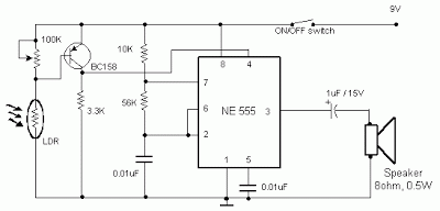
Simple Light Sensor Alarm circuit with NE555

Occurring this schema sent out an alarm when its LDR sensor is exposed to light by sun or lamp. A 555 stable multivariate was used here which sent signal a tone of about 1kHz upon detecting light.The sensor when exposed by light completes the schema and makes the 555 oscillate at about 1kHz with transistor to drive current.

The sensor is also shown in the schema diagram. It has to placed making an angle of about 30 – 45 degrees to the ground.

 light sensor alarm schema with ne555
 Sensitivity can be adjust with P1.
 This makes the sun light to flow through it to the ground and prevents the alarm from going on due to the stored light on the sensor
Read More