Showing posts with label electronic. Show all posts

Thursday, November 13, 2014

741 op amp bassed Alarm project electronic circuit with explanation


A very simple alarm project electronic circuit can be designed using a common 741 operational amplifier IC and some other common electronic parts . As you can see in the schematic circuit , this alarm project is activated by some normal open contacts , connected in parallel . If one of those contact is closed the alarm will sound .
This alarm project is composed from an audio frequency generator , a small audio amplifier stage and a small command stage .

The audio frequency generator is designed using a 741 operational amplifier ( or some other similar type ) .The T2 and T2 transistors forms a small audio amplifier and the normal opened contacts I1to I3 forms the command stage ( you can use how many contacts you need ).
In stand-by mode when all contacts are opened T1 transistor is locked and the alarm is inactive . If one of the contact is closed T1 transistor will activate the relay that will activate alarm . One the alarm starts to sound it can not be stopped until the I contact will be opened ( the circuit will be unplugged from the power source) .

The relay used in this project must have a 12 volts nominal voltage ( 10 volts activation) with a maximum working current of 10-30mA.
This circuit project must be powered from a 12 volt DC power supply .

Read More

Tuesday, November 4, 2014

Simple Security Door Electronic Key

It is a relatively simple circuit of electronic lock of safety with code of 7 digits. It should is given attention in the time that will be stepped the keys, that shape code and it does not exist it delays. With the right step of keys and if code is right then is activated exit Q7 for roughly 4 seconds, driving the transistor Q2, which with the line can drive one relay, for the opening of door, or any other circuit.

Security Door Electronic Key Circuit diagram :

Electronic

With LED D we can have optical clue of activation. The code of circuit, as it has been given have been:1704570 but can change, if we change the connections between in the exits of IC1 and the switches.

Parts List :
  • R1-7=4.7Kohm
  • R8=15Kohm
  • R9=1Mohm
  • R10-13=10Kohm
  • R11=100ohm
  • R12=220Kohm
  • R14=1.2Kohm
  • C1-3=100nF 100V
  • C2=4.7uF 25V
  • D1-2=1N4148
  • D3=RED LED 3mm
  • IC1=4022
  • Q1=BS170
  • Q2=BD679
  • S1-10=Push button or keyboard

Read More

Monday, November 3, 2014

FAIRCHILD SEMICONDUCTOR FMS6418B ELECTRONIC DIAGRAM


FAIRCHILD SEMICONDUCTOR FMS6418B ELECTRONIC DIAGRAM

This part consists of a triple 6th order filter with selectable 33MHz or 8MHz frequencies. At any given time, the input signal’s DC levels must be between 0.0V and 1.3V to utilize the optimal headroom and to avoid clipping on the outputs. The 220 ?F capacitor coupled with the 150 ? termination forms a high pass filter that blocks the DC while passing the video frequencies and avoiding tilt. Lower values such as 10 ?F would create a problem. By AC coupling, the average DC level is zero.

Thus, the output voltages of all channels will be centered around zero. Alternately, DC coupling the output of the FMS6418B is allowable. There are several trade-offs: The average DC level on the outputs will be 2V; each output will dissipate an additional 40mW nominally; The application will need to accommodate a 1V DC offset sync tip; And it is recommended to limit one 150 ? load per output.
Read More

Sunday, November 2, 2014

LONG RANGE FM TRANSMITTER ELECTRONIC DIAGRAM


LONG RANGE FM TRANSMITTER ELECTRONIC DIAGRAM

This circuit works optimally by adding RF amplifier and antenna. Here is the schematic diagram :

Parts list :
  •     Diode D1 : BB109
  •     Resistor R1 : 10k ohm
  •     Resistor R2 : 100k ohm
  •     Resistor R3 : 180k ohm
  •     Resistor R4 : 4K7
  •     Resistor R5 : 15k ohm
  •     Resistor R6 : 68 ohm
  •     Resistor R7 : 470 ohm
  •     Resistor R8 : 39k ohm
  •     Resistor R9 : 10 ohm
  •     VR1 : 47k ohm
  •     VR2 : 22 ohm
  •     Capacitor C1-C3, C8 : 0.1 uF
  •     Capacitor C4 : 4.7 pF
  •     Capacitor C6 : 0.01 uF
  •     Capacitor C7 : 5.6 nF
  •     Capacitor C9 : 100 pF
  •     Transistor T1: BF494
  •     Transistor T2:2N3866
  •     Trimmer VC1-VC2 : 50p
  •     L1 : 4 round 20 cables SWG in plastic with 8mm diameter
  •     L2 : 2 round 24 cables SWG
  •     L3 : 7 round 24 cables SWG in plactic with 4mm diameter
  •     L4 : 7 round 24 cables SWG in ferrid bead


Read More

SOFT START MECHANISM FOR L200 VOLTAGE REGULATOR ELECTRONIC DIAGRAM

SOFT START MECHANISM FOR L200 VOLTAGE REGULATOR ELECTRONIC DIAGRAM

Ic (constant current) is charge capacitor C, where Ic = Vsc/R.

The output reaches its nominal value after the time ton. Vo-Vsc=(Ic.ton)/C.

ton=C.[(Vo-0.45)/0.45].R = CVoR/0.45.

Vo follows the voltage in pin 2 at less than 0.45 volt. It is because voltage of more than 0.45 V can’t be produced between pin 2 and pin 5.
Read More

20W CLASS A POWER AMPLIFIER ELECTRONIC DIAGRAM


20W CLASS-A POWER AMPLIFIER ELECTRONIC DIAGRAM

The 0.25 Ohm resistor should cause little grief (4 x 1 Ohm 1W resistors in parallel), but some experimentation may be needed here, since the base-emitter voltage of the BC549 determines the current. This circuit works by using the BC549 to steal any excess base current from the compound pair. As soon as the voltage across the 0.25 Ohm resistor exceeds 0.65V, the transistor turns on and achieves balance virtually instantly.

The 1k trimpot in the collector of the first LTP transistor allows the DC offset to be adjusted. The nominal value is around 400 ohms, but making it variable allows you to set the output DC offset to within a few mV of zero.
Read More

Friday, September 5, 2014

Electronic Wiring diagram Schematic symbols 2


Here I have given more symbols of schema diagrams.More symbols will be given in the future


Read More

Monday, September 1, 2014

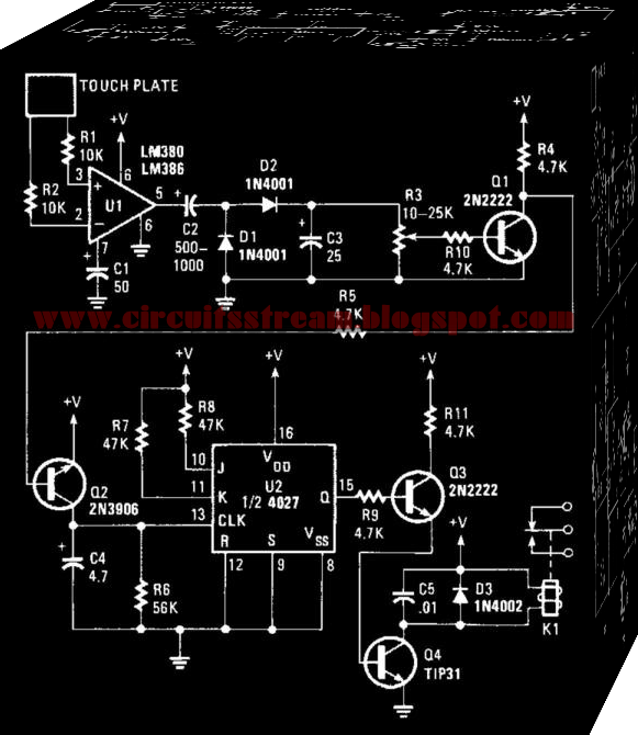
Electronic Touch Switch 1 Wiring diagram Schematic

This is an Electronic Touch Switch 1 Circuit Diagram. This switch reacts to the touch of a finger to turn lights and/or appliances on or off. The device uses the human body as an antenna to pick up 60-Hz hum, which is applied to a metal plate by your finger. The signal is fed to the input of Ul, an LM380 audio-power amplifier. An LM386 should work as well. 
 

 Electronic Touch Switch 1 Circuit Diagram


 electronic touch switch 1 circuit diagram
 
The 60-Hz output from the amplifier is rectified by Dl and D2, then filtered by C3. Potentiometer R3 sets the trigger voltage used to saturate Ql. When Ql turns on, the collector end of R4 goes almost to ground and provides the needed voltage to turn on Q2. Transistor Q2 turns on and clocks. 
 
The flip-flop is configured for toggle-mode operation, so its output switches states with each clock pulse. The 4027 (U2) is wired to toggle by tying the J and inputs high and the set and resets low. Transistor Q3 is connected to the Q output through the 4.7-KOhmhm resistor. Transistor Q3 drives Q4, the relay driver. Be sure that the load does not exceed the relay ratings.
Read More

Saturday, August 30, 2014

Electronic siren circuit


This is an electronic siren.you can use this one to your security systems or burglar alarms.so be creative then you can build up a fantastic creation.


* A 12 V battery or a a well regulated 12V DC power supply can be used to power the schema.
* Assemble the schema on a good quality PCB or common board.
* The switch S1 can be used to activate the alarm.
* The switch S2 can be used as a power switch.
* You can experiment on the tone of alarm by using different values for C2 and R8.

Read More