Showing posts with label dc. Show all posts

Monday, January 26, 2015

DC Coupled Audio Amplifier

Designs for audio amplifiers with DC coupling to the load are not often encountered these days, even though they offer definite advantages. One advantage is that there is no need for the complication of a second (symmetric) power supply; another is good frequency and phase response. Also, no special electrolytic capacitors are needed for voltage stabilisation, and switch-on ‘thump’ is much reduced. To try to rescue this class of circuit from obscurity the author has designed a headphone amplifier working along the lines illustrated in Figure 1.

DC-Coupled Audio Amplifier Circuit Diagram


It consists of a voltage divider, a voltage follower and the loudspeaker in the headphones, whose other side is connected to the junction of two electrolytic capacitors, providing the virtual earth. The potential at this point is, of course, half the supply voltage. All we need to do now is suitably couple in the audio signal to be amplified. Figure 2 shows a practical realisation of this idea in the form of a stereo headphone amplifier. The amplifier itself consists of IC1 and P1, R3 and R4 (giving a gain of 11).

DC Coupled Audio Amplifier Circuit Diagram


This part of the circuit demands no further explanation, and the same goes for the voltage divider mentioned above, formed by R1a and R1b. The signal is coupled in via the potentiometers. C2 and R2 have a special purpose: C2 connects the bottom end of the potentiometers (ground for the input signal) to the virtual earth. However, this capacitor creates a feedback path which can lead to oscillation of the amplifier under some circumstances. R2 damps this tendency to oscillate.
 
It is possible to calculate suitable values for these components, but it is better to determine them by experiment. C2 must be sufficiently large that stray electric fields do not cause unacceptable hum at the output. R2 must be sufficiently large that the voltage at the amplifier’s virtual earth stabilises quickly enough after switch-on. The polarity of the electrolytic is unimportant as no significant voltage appears across the network. It is possible to try the circuit out with the C2/R2 network shorted and observe the behaviour of the circuit at switch-on using an oscilloscope. Depending on the degree of asymmetry in the circuit, the voltage at the virtual earth point can take a considerable time to stabilise.


Read More

Thursday, December 11, 2014

AC to DC Schematic

  1. Classic Plus and Minus DC Power Supply - produces both a positive 15v and a negative 15v from a 20vac wall adapter.
  2. AC to DC Boost Converter with PFC - Implementation of a AC to DC Boost Converter with power factor correction.
  3. Classic Linear 5v Supply Using 6.3vac Transformer - Circuit consists of an iron core transformer, a bridge rectifier, a filter capacitor and a voltage regulator.
  4. AC-to-DC converter circuit utilizing IGBTs - AC-to-DC converter furnishing a regulated DC-output voltage from an AC-input supply voltage
  5. Non-isolated Off-line AC to DC Power Supply - Efficient circuit can provide up to 100ma of a regulated 5 volts from an AC power.
Read More

Thursday, November 13, 2014

DC Motor Speed Controller

This circuit takes advantage of the voltage drop across bridge rectifier diodes to produce a 5-position variable voltage supply to a DC fan or other small DC motor. It is not as efficient as a switch-mode circuit but it has the virtues of simplicity and no switching hash. The four full-wave bridges are connected so that each has two pairs of series diodes in parallel, giving a voltage drop of about 1.4V, depending on the load current.Circuit diagram:
DC Motor Speed Controller Circuit Diagram

The rotary switch should have "make before break" contacts which should be rated to take currents up to about an amp or so. For higher currents, higher rated bridge rectifiers and a suitably rugged rotary switch (or solenoids) will be required. If you want smaller voltage steps, you could use the commoned AC inputs on the bridge rectifiers to give intermediate steps on the speed switch.
Author: Stephen Butcher
Read More

Wednesday, November 12, 2014

LT3433 based Step Up Step Down DC to DC Converter Circuit Diagram circuit with explanation


The illustration provides below schemes 8V-60V to 12V Converter Circuit Diagram. It uses LT3433, an automatic step up and step down switching regulator IC with 4V to 60V input voltage which can be useful in automotive electronics using various wide input voltage range.

According to the LT3433 datasheet, this Automatic Step-Up and Step-Down Conversion device is a 200kHz fixed frequency current mode switching regulator using a single inductor which can be applied in applications such as wall adapter powered systems and battery power voltage buffering.

Read completely about Step Up/Step Down DC to DC Converter Circuit Diagram using LT3433 here in pdf archive (source: linear.com)

Read More

Friday, October 17, 2014

Versatile DC DC Converter

Here is a versatile power coupler that connects a device to 5V-19V DC generated from AC mains by a power adaptor. Power adaptors come in different voltage outputs like 5V (for mobile phones), 12V (for external hard drives) and 19V (for laptops). Sometimes the power adaptor may have a voltage rating higher than the required voltage. With the converter circuit given here, the adaptor can be used to power any device at a lower voltage. For instance, by using a 19V laptop adaptor, you can power a TTL circuit at 5V. There can also be other instances when one needs a 3V or 6V supply. All these and many other intermediate voltages are easily possible with this versatile converter circuit when used together with any off-hand power adaptor.

Versatile DC-DC Converter Circuit diagram :

Versatile
Versatile DC-DC Converter Circuit diagram

Fig. 1 shows the circuit of the DC-DC converter. Smooth reduction in the voltage is achieved using the LM317 regulator IC. The complete unit can fit inside a piece of a glue stick tube.

Adjusting variable resistor VR1 gives the desired output voltage. The output voltage is read using a 0-100µA ammeter, whose series resistance R* is chosen such that the maximum desired voltage could be covered. For instance, if full-scale deflection (FSD) current of the meter is 100 µA and you need an output voltage of up to 15V, then R* = 15/0.0001 = 150 kΩ. The desired value of R* is obtained by using 150-kilo-ohm preset VR2. 

Use of a variable resistor which also has an on/off switch like the one in old radios is recommended. It will cut off the coupler from the input power supply without having to accomodate an additional switch. Also, use a heat-sink with LM317 to handle the desired amount of power.

Proposed-assembly

Assemble the circuit on a small general-purpose PCB and enclose in a suitable case. Fit the entire PCB inside a glue stick tube as shown in Fig. 2. Affix the female and male connectors on the opposite ends and place the ammeter in between the stick tube. You can directly read the output voltage on the ammeter after due calibration.

Note. You can use a suitable VU meter instead of 0-100µA ammeter and calibrate accordingly.
Read More

Sunday, September 21, 2014

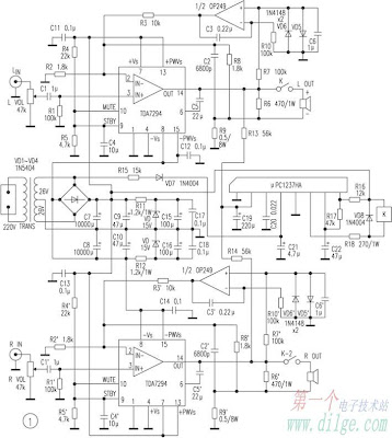
Amplifier current negative feedback TDA7294 DC Servo

TDA7294

In the field of consumer reports electronics products reviews, product size, weight is toward smaller, lighter direction, high-power single-chip audio power amplifier needs of increasingly prominent, TDA7294 is currently the best performance, the biggest single-chip audio power amplifier One.

It consists of the European SGS-THOMSON Italian-French company in accordance with discrete components A and B audio amplifier circuit design from classic. Its former low-level noise, low distortion of the bipolar transistor circuit, at the end of a high-pressure, high current DMOS output of the buffer, it has bipolar circuit sounds pure merit, have large current high voltage FET Driver output characteristics.

Since 1998 TDA7294 introduced to China so far, I believe that many enthusiasts have been TDA7294 delicate taste, natural sound. Regrettably, however, is that they have heard only negative feedback is standard voltage of the voice amplifier.

And negative feedback amplifier voltage than current negative feedback amplifier as excellent transient nonlinear distortion and intermodulation distortion characteristics, the frequency amplifier curve flat, high and low frequency response more exhibition wide; more important is that circuit Will load impedance into the feedback network, it can change the speakers of such fierce resistance to the load compensation, coupled with stable and reliable performance, than the negative feedback voltage amplifier has more advantages, the current negative feedback current amplifier is widely For the modern high-fidelity audio amplifier.

Figure 1 circuit is an excellent performance, improve the design of the fever-100 W × 2 DC Servo Amplifier current negative feedback stereo amplifier, formed by the two TDA7294, the frequency response of 10 Hz ~ 100kHz. The use of sophisticated audio Yun-double as the two-channel amplifier DC Servo Amplifier output. Speakers from the protection of ASIC μPC1237HA driver completed the relay switch-mute and amplifier output DC offset protection, and other speakers. When the AC power plug, the relay will be delayed for some time speakers access amplifier; disconnecting the AC power when, μPC1237HA detected exchange loss, immediately disconnect the speaker to relay, the amplifier is the complete elimination of the set, Shutting down the transition process the impact of noise on the speakers.

In actual use, taking into account the electricity grid fluctuations Rectifier amplifier output voltage ± Vs volatile, in order to avoid over-voltage and high temperature in the state of damage TDA7294 (Note pressure in the temperature of 25 ℃ under the conditions, if the temperature exceeds 25 ℃, TDA7294 the value will subsequently reduce the pressure), the exchange recommended power supply voltage transformer CT-AC26V × 2.

Listen:

Speaker to use B & W601, CD machine Marantz CD-19, compared TDA7294 amplifier for the negative feedback standard voltage lines. Software programs at Cai Qin, "the film" test the human voice, Mutebutsi trial String, RRs "Tutti" dynamic test, Rubinstein "Chopin Nocturne" trial piano.

The results are as follows:

In a dynamic sense of speed, the two amplifier very close, but the sound on the current negative feedback is obviously more sweet; the string, the human voice like the rendering software for a warmer, the details of the re-orientation; due to current negative feedback circuit Impedance of the compensation, the low-band high-impedance output has been strengthened, so dive in the low-frequency and intensity of the depth occupied obvious advantage.

Current negative feedback in addition to direct stereo amplifier for CD, VCD, DVD, and other music source amplifier, but also with audio processing unit for use by different combinations of the playback effect.

Read More

Saturday, September 13, 2014

LM1458 and 2N3055 DC Variable Regulator Power Supply

LM1458 and 2N3055 DC Variable Regulator Power Supply

Power ascendancy is adjustable 3-25 volts and is accepted bound to 2 amps as shown,but may be up to 3 amps in a baby accepted faculty resistor by options (0.3 ohm). 2N3055 transistors 2N3053 and should be in the sinks. actual hot appropriate now and resistor should be rated at 3 watts or more. voltage that is controlled by 1 / 2 of the op amp LM1458 or 1458-AMP. It may be commissioned in the ambit below, but sources advance pressure. dispensing pin 8 is bound to 30 VDC, which can access by 6.2 volt zener or 5.1 resistor K alternation is 8 pin. best voltage DC accumulation for 1458 and 1558 are 36 and 44, respectively. ability agent should be. As can be accepted in the accepted voltage. Enter at atomic 4 volts college than the adapted achievement voltage but not beat the best bulk of op-AMP beneath low amount conditions. Agent is apparent as a centermost broke 25.2 volt AC / AMP 2 units to advice ascendancy the 24 volts at 0.7 amps, 15 volts at 2 amps or 6 volts at 3 amps. Achievement AMP 3 is the centermost of the water. agent that changes the 18 volt position. All apparatus charge accept a Radio berth barring of LM1458 op-AMP.
Read More

Thursday, September 11, 2014

DC to DC converter 1 5V to 3V Wiring diagram Schematic

A DC-DC converter 1.5V to 3V Circuit Diagram to reduce the voltage is easy, but the situation becomes more complicated when we have to increase the voltage. This simple scheme generates a voltage 3Vdc from 1.5 VDC, which can be a single stack. We can get good results by modifying an multivibrator using two transistors, the frequency converter is approximately 130 kHz. The inductance value can be calculated experimentally.

DC / DC converter 1.5V to 3V Circuit Diagram

DC


Schottky diode VD1 can be replaced by any other similar characteristics.

For further stabilization of the output voltage can be placed one Zener 3V - 3.3V. This scheme can be used to feed a power LED device, a micro-controller, Arduino, etc. ..

List of Components
R1, R3: 1K
R2: 2K2
C1: 470pF
C2: 100uF / 3.3V
C3: 1000uF
L1: 470UH
VD1: 15MQ040
VT1, VT2: BC547
Read More

Monday, August 25, 2014

Versatile DC DC Converter

Here is a versatile power coupler that connects a device to 5V-19V DC generated from AC mains by a power adaptor. Power adaptors come in different voltage outputs like 5V (for mobile phones), 12V (for external hard drives) and 19V (for laptops). Sometimes the power adaptor may have a voltage rating higher than the required voltage. With the converter schema given here, the adaptor can be used to power any device at a lower voltage. 

For instance, by using a 19V laptop adaptor, you can power a TTL schema at 5V. There can also be other instances when one needs a 3V or 6V supply. All these and many other intermediate voltages are easily possible with this versatile converter schema when used together with any off-hand power adaptor.


Versatile
Versatile DC-DC Converter Circuit diagram

Fig. 1 shows the schema of the DC-DC converter. Smooth reduction in the voltage is achieved using the LM317 regulator IC. The complete unit can fit inside a piece of a glue stick tube.
Adjusting variable resistor VR1 gives the desired output voltage. The output voltage is read using a 0-100µA ammeter, whose series resistance R* is chosen such that the maximum desired voltage could be covered. For instance, if full-scale deflection (FSD) current of the meter is 100 µA and you need an output voltage of up to 15V, then R* = 15/0.0001 = 150 kΩ. The desired value of R* is obtained by using 150-kilo-ohm preset VR2. 

Use of a variable resistor which also has an on/off switch like the one in old radios is recommended. It will cut off the coupler from the input power supply without having to accomodate an additional switch. Also, use a heat-sink with LM317 to handle the desired amount of power.

Proposed-assembly

Assemble the schema on a small general-purpose PCB and enclose in a suitable case. Fit the entire PCB inside a glue stick tube as shown in Fig. 2. Affix the female and male connectors on the opposite ends and place the ammeter in between the stick tube. You can directly read the output voltage on the ammeter after due calibration.

Note. You can use a suitable VU meter instead of 0-100µA ammeter and calibrate accordingly.

Copyright : EFY
Read More

Sunday, August 24, 2014

Ac to DC Converter Wiring diagram Schematic

This Ac to DC Converter Circuit Diagram includes a PMOS enhancement-mode FET input buffer amplifier, coupled to a classical absolute value schema which essentially eliminates the effect of the forward voltage drop across diodes D1 and D2. 

Ac to DC Converter Circuit Diagram

Ac

Read More