Sunday, August 31, 2014

Simple Light Sensor Alarm circuit with NE555

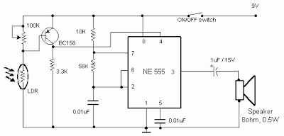
Occurring this schema sent out an alarm when its LDR sensor is exposed to light by sun or lamp. A 555 stable multivariate was used here which sent signal a tone of about 1kHz upon detecting light.The sensor when exposed by light completes the schema and makes the 555 oscillate at about 1kHz with transistor to drive current.

The sensor is also shown in the schema diagram. It has to placed making an angle of about 30 – 45 degrees to the ground.

 light sensor alarm schema with ne555
 Sensitivity can be adjust with P1.
 This makes the sun light to flow through it to the ground and prevents the alarm from going on due to the stored light on the sensor

Long Delay Stop Switch

Long-Delay Stop Switch Circuit Diagram. Presettable times for train stops in stations are indispensable if you want to operate your model railway more or less realistically according to a timetable. This schema shows how a 555 timer can be used with a relatively small timing capacitor to generate very long delay times as necessary by using a little trick (scarcely known among model railway electronic technicians): pulsed charging of the timing net-work. Such long delays can be used in hidden yards with through tracks, for instance.  As the timer is designed for half-wave operation, it requires only a single lead to the transformer and one to the switching track or reed contact when used with a Märklin AC system (H0 or H1). The other lead can be connected to any desired grounding point for the common ground of the track and lighting diagram.

Long-Delay
Long-Delay Stop Switch Circuit Diagram

As seen from the outside, the timer acts as a monostable flip-flop. The output (pin 3) is low in the quiescent state. If a negative signal is applied to the trigger input (pin 2), the output goes high and C4 starts charging via R3 and R4. When the voltage on C4 reaches 2/3 of the supply voltage, it discharges via an internal transistor connected to pin 7 to 1/3 of the supply voltage and the output (pin 3) goes low. The two threshold values (1/3 and 2/3) are directly proportional to the supply voltage. The duration of the output signal is independent of the supply voltage: t= 1.1(R4 + R5) × C4 

if the potentiometer is connected directly to the supply line (A and B joined). The maximum delay time that can be generated using the component values shown in the schematic diagram is 4.8 minutes. How-ever, it can be increased by a factor of approximately 10 if the timing network is charged using positive half-waves of the AC supply voltage (reduced to the 10–16-V level) instead of a constant DC voltage. 

The positive half-waves of the AC voltage reach the timing network via D2, the transistor, and D3. Diode D3 prevents C4 from being discharged between the pulses. The total resistance of R4 and R5 should not be too high (no more than 10 MΩ if possible), since electrolytic capacitors (such as are needed for C4) have significant leakage currents. Incidentally, the leakage current of aluminium electrolytic capacitors can be consider-ably reduced by using a supply voltage well below the rated voltage. Capacitor C6 is intended to suppress noise. It forms a filter network in combination with an internal voltage-divider resistor.
If a vehicle happens to remain standing over the reed switch so the magnet holds the contacts constantly closed, the timer will automatically be retriggered when the preset delay times out. In this case the relay armature will not release and the locomotive will come to the ‘end of the line’ in violation of the timetable. This problem can be reliably eliminated using R6, R7 and C5. This trigger schema ensures that only one trigger pulse is generated, regardless of how long the reed switch remains closed. RC network R8/C7 on the reset pin ensures that the timer behaves properly on switch-on (which is far from being something to be taken for granted with many versions of the 555 or 556 dual timer).
Reed switches have several special characteristics that must be kept in mind when fitting them. The contact blades, which are made from a ferromagnetic material, assume opposite magnetic polarities under the influence of a magnetic field and attract each other. Here the position and orientation of the magnet, the distance between the magnet and the reed switch, and the direction of motion of the magnet relative to the switch are important factors. The fragility of the glass hous-ing and the thermal stress from soldering (stay at least 3 mm away from the glass housing) require a heat sink to be used between the soldering point and the glass/metal seal. A suitable tweezers or flat-jawed pliers can be used for this pur-pose. If you need to bend the leads, use flat-jawed pliers to protect the glass/metal seal against mechanical stresses. 

Matching magnets in various sizes are available from toy merchants and electronics mail-order firms. They should preferably be fitted underneath the loco-motive or carriage. However, the magnet can also be fitted on the side of a vehicle with a plastic body. In this case the reed switch can be hidden in a mast, bridge column or similar structure or placed in a tunnel, since the distance must be kept to less than around 10 mm, even with a strong magnet. If fitting the schema still presents problems (especially with Märklin Z-gauge Mini-Club), one remedy is to generate the trigger using a unipolar digital Hall switch, such as the Siemens TLE4905L or Allegro UGN3120. To avoid coupled-in interference, the stop timer should be fitted relatively close to the Hall sensor (use screened cable if necessary). Pay attention to the polarity of the magnet when fitting it to the bottom of the vehicle. With both types of sensors, the South pole must point toward the front face of the Hall IC (the face with the type marking). The North pole is sometimes marked by a dab of paint. Generally speaking, the polarity must be determined experimentally. 

Fitting the schema is not a problem with Z-gauge and 1-gauge tracks, since the distance between the iron parts (rails) and the Hall switch is sufficiently large. In an HO system, some modifications must be made to the track bed of the Märklin metal track. Cut a suitably sized ‘window’ between one wheel rail and the centre rail in order to prevent secondary magnetic diagram from interfering with the operation of the sensor. Keep the distance between the magnet and the case of the Hall switch between 5 and 10 mm, depending on the strength of the magnet, to ensure reliable actuation.

On Off Touch Switch Circuit

The modern mechanic switches are improved concerning of old technology. We need however many times to replacement some old switch or to check currents bigger than the durability of certain switches or simple we need something with modern appearance. For he and different reasons is essential the up schema. It is simple in the manufacture and the materials that use they exist everywhere.


Parts:

R1 = 3.3M
R2 = 3.3M
R3 = 10K
R4 = 1K
C1 = 10nF-63V
D1 = 1N4007
D2 = Red LED
Q1 = BC547
IC1 = NE555
RL1 = 12V Relay


This schema is based on the well known timer IC 555 (IC1), which drives a relay of which the contacts play the role of switch. The metal surfaces can have what form we want, but it should they are clean and near in the schema. In order to it changes situation it suffices touch soft somebody from the two plates. Plate MP1 in order to the contacts of RL1 close [ON], or plate MP2 in order to the contacts of RL1 open [OFF]. The current that RL1 will check depended from his contacts. The Led D2 turns on when the switch they are in place ON and the contacts of RL1 closed. Two small pieces of metal can be used instead of MP1 – MP2. Because MP = Metal Plate.

L144 Instrumentation amplifier

Three-amplifier circuit consumes only 135 /tW of power from a ±1 V power supply. With a gain of 101, the instrumentation amplifier is ideal in sensor interface and biomedical preamplifier applications. The first stage provides all of the gain while the second stage is used to. provide common mode rejection and double-ended to single-ended conversion.


Saturday, August 30, 2014

High Power LEDs up to 15 Amperes Wiring diagram Schematic

This High Power LEDs up to 15 Amperes Circuit Diagram employs a simple scheme that limits the current flow to the LED, you can easily modify the schema, and can change the power just replacing the value of R2. You can use a DC source of any tensions between 9V to 15V.Para powers or other LEDs just use the approximate formula:

Current (I) = 0.8/R2 where I is the current specified by the LED manufacturer. Value of I this conductor is 10A. Use R2 = 0.8/Current formula (I) to determine R2.

High Power LEDs up to 15 Amperes Circuit Diagram

High


Parts List

Q1 2N3055 or similar NPN transistor
R1 1W 220ohms
D1, D2 1N4001 silicon diode or rectifier

See R2 power for each LED

R2 for 1W LED 1W 2.7ohms
R2 LED to 1.5 ohms 1W 3W
5W LED R2 to 0.6 ohms or 2 x parallel 1.2-ohms/1W

Combine stereo input to one output

Here , I will give a circuit of schemes that are used to combine 2 pieces input or stereo to 1 input mono. Why 2 inputs in to one because, if we need a stereo amplifier we want to become a stronger by combining the two input into one input, so that a higher power output. Actually without any circuit above we can combine stereo amplifier into mono, but the sound output less than the maximum , need for this additional combiner circuit.
 btl amplifier
Part List =
R1______150K
R2______920R
R3______150K
R4______920R
R5______920R
U1______NE5532

For balance _: R1 / R2=R3 / R4
For balance _: R1 = R3
Gain ______: R5 / R1 = R5 / R3

Steam Whistle Wiring diagram Schematic

This is a simple Steam Whistle Circuit Diagram. This schema consists of six square wave oscillators. Square waves are made up of a large number of harmonics. If six square waves with different frequencies are added together, the result will be a signal with a very large number of frequencies. When you listen to the result you’ll find that it is very similar to a steam whistle. The schema should be useful in modelling or even in a sound studio.

Steam Whistle Circuit Diagram

Simple
Simple Steam Whistle Circuit Diagram

This schema uses only two ICs. The first IC, a 40106, contains six Schmitt triggers, which are all configured as oscillators. Different frequencies are generated by the use of different feedback resistors. The output signals from the Schmitt triggers are mixed via resistors. The resulting signal is amplified by IC2, an LM386. This IC can deliver about 1 W of audio power, which should be sufficient for most applications. If you leave out R13 and all components after P1, the output can then be connected to a more powerful amplifier. In this way a truly deafening steam whistle can be created. The ‘frequency’ of the signal can be adjusted with P2, and P1 controls the volume.


Streampowers

Electronic siren circuit


This is an electronic siren.you can use this one to your security systems or burglar alarms.so be creative then you can build up a fantastic creation.


* A 12 V battery or a a well regulated 12V DC power supply can be used to power the schema.
* Assemble the schema on a good quality PCB or common board.
* The switch S1 can be used to activate the alarm.
* The switch S2 can be used as a power switch.
* You can experiment on the tone of alarm by using different values for C2 and R8.

Battery powered Headphone Amplifier

Some lovers of High Fidelity headphone listening prefer the use of battery powered headphone amplifiers, not only for portable units but also for home "table" applications.


Battery-powered


Parts:

P1_____________22K Dual gang Log Potentiometer (ready for Stereo)

R1_____________15K 1/4W Resistor
R2____________100K 1/4W Resistor
R3____________100K 1/2W Trimmer Cermet
R4_____________47K 1/4W Resistor
R5____________470R 1/4W Resistor
R6____________500R 1/2W Trimmer Cermet
R7______________1K 1/4W Resistor
R8,R9__________18K 1/4W Resistors
R10,R11_________2R2 1/4W Resistors
R12____________33R 1/4W Resistor
R13_____________4K7 1/4W Resistor

C1,C2__________10µF 25V Electrolytic Capacitors
C3,C5_________100nF 63V Polyester Capacitors
C4,C6_________220µF 25V Electrolytic Capacitors

Q1,Q2,Q5______BC560C 45V 100mA Low noise High gain PNP Transistors
Q3,Q4_________BC550C 45V 100mA Low noise High gain NPN Transistor
Q6____________BC327 45V 800mA PNP Transistor
Q7____________BC337 45V 800mA NPN Transistor

SW1____________SPST slide or toggle Switch

J1_____________RCA audio input socket
J2_____________6mm. or 3mm. Stereo Jack socket

B1_____________6V Battery (4xAA or AAA Alkaline or rechargeable cells, etc.)


Output power can reach 100mW RMS into a 16 Ohm load at 6V supply with low standing and mean current consumption, allowing long battery duration.
The single voltage gain stage allows the easy implementation of a shunt-feedback schemary giving excellent frequency stability.


Notes:


* For a Stereo version of this schema, all parts must be doubled except P1, SW1, J2 and B1.
* Before setting quiescent current rotate the volume control P1 to the minimum, Trimmer R6 to maximum resistance and Trimmer R3 to about the middle of its travel.
* Connect a suitable headphone set or, better, a 33 Ohm 1/2W resistor to the amplifier output.
* Switch on the supply and measure the battery voltage with a Multimeter set to about 10Vdc fsd.
* Connect the Multimeter across the positive end of C4 and the negative ground.
* Rotate R3 in order to read on the Multimeter display exactly half of the battery voltage previously measured.
* Switch off the supply, disconnect the Multimeter and reconnect it, set to measure about 10mA fsd, in series to the positive supply of the amplifier.
* Switch on the supply and rotate R6 slowly until a reading of about 3mA is displayed.
* Check again the voltage at the positive end of C4 and readjust R3 if necessary.
* Wait about 15 minutes, watch if the current is varying and readjust if necessary.
* Those lucky enough to reach an oscilloscope and a 1KHz sine wave generator, can drive the amplifier to the maximum output power and adjust R3 in order to obtain a symmetrical clipping of the sine wave displayed.


Technical data:

Output power (1KHz sinewave):
16 Ohm: 100mW RMS
32 Ohm: 60mW RMS
64 Ohm: 35mW RMS
100 Ohm: 22.5mW RMS
300 Ohm: 8.5mW RMS
Sensitivity:
160mV input for 1V RMS output into 32 Ohm load (31mW)
200mV input for 1.27V RMS output into 32 Ohm load (50mW)
Frequency response @ 1V RMS:
flat from 45Hz to 20KHz, -1dB @ 35Hz, -2dB @ 24Hz
Total harmonic distortion into 16 Ohm load @ 1KHz:
1V RMS (62mW) 0.015% 1.27V RMS (onset of clipping, 100mW) 0.04%
Total harmonic distortion into 16 Ohm load @ 10KHz:
1V RMS (62mW) 0.05% 1.27V RMS (onset of clipping, 100mW) 0.1%
Unconditionally stable on capacitive loads


Friday, August 29, 2014

Build a Uhf TV Preamplifier Wiring diagram Schematic

Build a UHF TV Preamplifier Circuit Diagram. An inexpensive. antenna-mounted, UHF TV preamplifier can add more than 25 dB of gain. The first stage of the preamp is biased for optimum noise, the second stage for optimum gain. Ll, L2 strip line `` J../8 part of PC board.

UHF TV Preamplifier Circuit Diagram

UHF

Small Audio Amplifiers Using LM386 and NE5534

Many electronic projects require the use of a small audio amplifier. Be it a radio transceiver, a digital voice recorder, or an intercom, they all call for an audio amp that is small, cheap, and has enough power to provide adequate loudness to fill a room, without pretending to serve a disco! About one Watt RMS seems to be a convenient size, and this is also about the highest power that a simple amplifier fed from 12V can put into an 8 Ohm speaker. A very low saturation amplifier may go as high up as 2 Watt, but any higher power requires the use of a higher voltage power supply, lower speaker impedance, a bridge schema, or a combination of those.

During my many years building electronic things I have needed small audio amps many times, and have pretty much standardized on a few IC solutions, first and and foremost the LM386, which is small, cheap, and very easy to use. But it does not produce high quality audio... For many applications, the advantages weigh more than the distortion and noise of this chip, so that I used it anyway. In other cases I used different chips, which perform better but need more complex diagram. Often these chips were no longer available the next time I needed a small amplifier.

When I last upgraded my computer, I replaced the old and trusty Soundblaster AWE 32 by a Soundblaster Audigy. The new card is better in many regards, but while the old one had an internal audio power amplifier, the new one doesnt! Thats bad news, because I have some pretty decent speakers for the PC, which are fully passive. So, I built a little stereo amp using two LM386 chips and installed it inside the computer, fed by the 12V available internally.

But then I wasnt satisfied. The LM386 might be suitable for "communication quality" audio, which is roughly the fidelity you get over a telephone, but for music its pretty poor! The distortion was awful. So, the day came when I decided to play a little more scientifically with small audio amps, looking for a way to get good performance with simple and inexpensive means.

I set up a test bench with a sine wave oscillator running at 1 kHz, an 8 Ohm speaker, 12V power supply, and the computer with the soundcard and Fast Fourier Transform software. One channel was connected to the oscillator together with the amplifier input, the other channel to the output and speaker. With this setup I measured the harmonic content of the audio signals. I did the tests at an output level of 0.1W, which is typical for moderately loud sound from a reasonably efficient speaker. Also, I used a music signal from a CD player to test the actual sound of each amplifier.

Circuit

As already said above, the main attraction of the LM386 is the extreme simplicity of its application schema. You can even eliminate R1 if the signal source is DC-grounded. If the speaker leads are long, you should add an RC snubber across the output to aid stability. Additionally, if you need higher gain (not necessary if the input is at line level), you can connect a 10uF capacitor between pins 1 and 8. Thats about all there is to it.

Now the bad news: This schema produced a very high level of distortion! The second harmonic measured just -28dB from the main output. The third harmonic was at -35dB, while the noise level was at -82dB. There were assorted high harmonics at roughly -45dB. With music, the distortion was really disturbing, and also the noise level was uncomfortably high. The power supply rejection is poor, so that some hum and other supply noise gets through. In short, this was a lousy performance!

Since I had used so many LM386s in my projects, I had several different variations. In my material box I found a slightly newer LM386N-1. So I plugged it into my test amplifier. It was even worse! The second harmonic was at -24dB, the third harmonic at -31dB, while the noise was a tad better at -84dB. Folks, thats a total harmonic distortion of almost 7%! And the 0.1W output level at which this was measured is where such a schema is about at its best...  The distortion can be plainly seen on the oscilloscope, and a visibly distorted waveform is about the most offending thing an audio designer can ever see!

Looking through my projects, I found one where I had used a GL386 chip. This is just a 386 made by another company. I unsoldered it and put it in my test amplifier. Surprise! It was dramatically better, with the second harmonic at -45dB, and the third at -57dB! The noise floor was -84dB, just like the LM386N-1. But even this level of distortion was plainly audible when listening to music. Thats roughly 0.6% THD. Some folks may consider it acceptable for music. I dont, but for communication equipment its fine. At this point, I decided to see if I could build a better amplifier, that doesnt become too complex nor expensive.

Circuit

This was the first attempt. A low distortion, fast slew rate, but easy to find and rather inexpensive operational amplifier, driving a simple source follower made of two small transistors. These transistors are not biased, so they work at zero quiescent current, in full class B. The only mechanism that works against crossover distortion here is the high slew rate of the OpAmp, which is able to make the distortion bursts during crossover very short. To say the truth, I didnt expect to get usable performance from this schema, and was really surprised when it worked much better than the 386! The second harmonic was at -77dB, the third at -79dB!

Also there were many high harmonics at roughly -84dB. That means a THD of about 0.015%.  The noise floor was down at the -120dB level! The power supply rejection was excellent, with no detectable feedtrough. Playing music, this amplifier sounded really good: No audible noise, and the distortion could be heard when paying attention to it, but I doubt that the average person would detect it! Not bad, for a bias-less design!

Just to see how important the slew rate of the OpAmp is, I pulled out the NE5534 and replaced it by a humble 741, which is many times slower. The result was dramatic: The second harmonic still good at -70dB, but the third harmonic was much worse, at -48dB. Also there were many high harmonics at the same -48dB level. Given that second harmonic distortion doesnt sound bad to most people, but third harmonic does, and high harmonics are even worse, it came as no surprise that the amplifier with the 741 sounded bad.

At low volume it sounded particularly bad! So I returned to the oscillator and measurement setup, testing at lower output power, and found that while the second and third harmonics followed the output, the high harmonics stayed mostly constant! So, at very low output, the high harmonics became very strong relative to the output. All this is the effect of the slower slew rate of the 741, which makes it less effective correcting the crossover distortion of the unbiased transistors. Interestingly, the noise floor of the 741 schema wasnt bad: -118dB.

Just for fun, I tried this schema with a third OpAmp: The TL071, which is good, but not as good as the 5534. The results: Second harmonic at -72dB, third and the high ones at -60dB, and the noise at -120dB. Its interesting that the second harmonic is much more suppressed than the third one. That must be a balancing effect of the symmetric output stage, and the better symmetry in the TL071 compared to other OpAmps.

Its worthwhile to note that this amplifier can be simplified a lot by using a split power supply. R1, R2, C1, C2 and C4 would be eliminated! But then you need the capacitor removed from C4 to bypass the negative supply line. The positive input of the chip goes to ground, while pin 4 and the collector of Q2 go to the negative supply. The rest stays the same. If you use a +-15V supply, the available RMS output power grows to over 10 Watt! Of course, you then need larger transistors. And since larger transistors are slower, the distortion will rise somewhat. An added benefit of a split supply is that the popping noise when switching on and off is eliminated.

Circuit

As the next experiment, I decided to get rid of the crossover distortion. For this purpose, I added a traditional adjustable bias schema with a transistor and a trimpot. Now I also had to add a current source, because with the bias schema there is no single point into which the OpAmp could put its drive current into both bases! I adjusted the bias for the best distortion, and this was really  a good one! The second harmonic was down right where the test oscillator delivered it, about -80dB, so I couldnt really measure it!

The third harmonic was at -84dB, and the best improvement was that the higher harmonics had simply disappeared! They were all below the noise floor, which stayed at -120dB. Actually, this noise floor seems to come from the soundcard A/D converter, so that the actual noise of this and the above amplifier may even be better! With music, this amplifier sounded perfect - clean and smooth. And Im pretty confident that the THD is well below the limits of my measurement setup, which is 0.01%.

The quiescent current was around 10mA. When lowering it to about 3mA, the high harmonics started to rise out of the noise floor. If you want to adjust the bias for the exact best quiescent current, there is a simple trick: Lift R4 from the output, and connect it to pin 6. Now the output stage has been left outside the feedback loop, and all its distortion will show up at the output. Watching the signal on an oscilloscope, or even better on a real time spectrum analyzer (soundcard and software), adjust the trimpot to the lowest distortion level.

Have a current meter in the supply line and make sure that you dont exceed 30mA or so of quiescent current, in order to keep the small transistors cool. But most likely the best distortion will be at a current lower than that. Once the adjustment is complete, return R4 to its normal position. Now the full gain and slew rate of the operational amplifier is used to correct the small remaining cross-over distortion of the output stage, and the distortion will certainly disappear from the scope screen, from your ears, and possibly fall below the detection level of the spectrum analyzer!

This schema can also be run from a split power supply, by exactly the same mods as for the previous schema. And since the transistors are properly biased, there isnt any significant distortion increase when using larger transistors. Be sure to use some that have enough gain - you have only a few mA of driving available, and with a +-15V power supply and an 8 Ohm speaker, there can be almost 2A of output current! So, you need a gain of 300 at least. There are power transistors in the 4A class that provide such gain, and these are good candidates. The other option is using Darlington transistors, which far exceed the gain needed here. But they will again increase the distortion, not very much, but perhaps enough to make it audible again.
Source: Streampowers
Simple Voice Scrambler Disguiser Wiring diagram Schematic

Simple Voice Scrambler/Disguise Circuit Diagram uses two balanced modulators to produce a DSB signal and then reinsert the carrier, except the carrier now has a different frequency. This causes an input signal to be distorted. A voice signal will be recognizable with this schema, but the original speakers` voice will not be identifiable with correct adjustments. Two LM324 op amps act as oscillators that are tuneable from 2 to 3.5 kHz. The frequencies are set with R12 and R13., T2, and T3 are 600 CT/600 audio.

 Voice Scrambler/Disguiser Circuit Diagram


Voice

Schematic Audio Power Amplifier with IC TDA2612

This amplifier circuit based on IC TDA2612 produced by siemens , minimum voltage require for this circuit is 10 Volts and amximum voltage require 35 volts DC. Power output 25 watt with 4 ohm impedance.Frequncy response 20Hz to 20kHz. Quiescent current is 70 mA. This is a mono circuit amplifier. See circuit below :


 You can use the circuit above at :
  • Car
  • Tuner
  • Pre amp Head
  • Pre amp Mic
  • Personal Computer 
  • Portable media Player
  • etc.
Some advantage of the circuit :
  • Fairly high voltage
  • Low noise sound output
  • Easy to make
  • Components are easy to find

Thursday, August 28, 2014

Strain Gauge measure the pressure or weight

Strain gauges are electronic components that serves to measure the pressure or weight. "Strain Gauge"was first discovered by Edward E. Simmons in 1983 in the form of metal foil that is insulif (isolation) attached to the body weight pressure to be measured. In principle, if the strain gauge given the pressure of the electrical resistance strain gauge will change because the process of deformation in the strain gauge the magnitude of change in electrical resistance that would follow the change of the received pressure strain gauge.

Preamplifier for RF Sweep Generator

Preamplifier for RF Sweep Generator Circuit diagram. The RF sweep frequency generator (‘wobbu-lator’) published in the October 2008 issue of Elektor has a receiver option that allows the instrument to be used as a direct conversion receiver. This receiver does however have a noise floor of only –80 dBm, which really should have been –-107 dBm to obtain a sensitivity of 1 µV. So, for a good receiver sommore gain is required. A wideband amplifie however, generates a lot of additional noisas well and as a consequence will not resuin much of an improvement.  As an experiment, the author developed a selective receiver with a bandwidth of about 4 MHz. Because a gain of at least 35 dB is required, the preamplifier consists of two amplifying elements. 

The input amplifier is designed around a dual gate MOSFET, type BF982. This component produces relatively little noise but pro-vides a lot of gain. The output stage uses a BFR91A for some additional gain. Preamplifiers where both the gate and the drain are tuned often struggle with feedback via their  internal capacitance. Here, the drain schema has a relatively low impedance, which prevents this from happening. In the prototype that was tested, the input and output are located at right angles with respect to each other to prevent inductive coupling (see photo). Despite the high gain, the amplifier was perfectly stable even without any shielding.  The two air-cored coils in the schema both consist of 4 turns and have an internal  diameter  of  6 mm,  made from 1-mm diameter silvered copper wire and with a tap after 1 turn.

Preamplifier for RF Sweep Generator Circuit diagram :
Preamplifier
Preamplifier for RF Sweep Generator Circuit Diagram
 
The amplifier is mainly intended for the 144 MHz amateur band, but with other coils can also be used for the FM broadcast band, for example. FM detection is achieved by tuning near the edge of the IF filter. At an offset of 15 kHz this is only a few dB lower than at the centre of the pass-band, so that damping is not noticeable. The measured sensitivity in the 2 m band was about 1 µV (6 dB).A good antenna always contributes to the reception, of course. A wideband (scanner) outdoor antenna will give good results. Adding this wobbulator/receiver option results in a nice monitor receiver. By setting the scan frequencies of the spectrum analyser to 144 and 146 MHz (or 148 MHz where applicable), any signal within this range is directly visible. When a signal is detected it is merely a case of clicking the scan stop button and then clicking on the signal in the display window using the right mouse button. 

After this, the receiver switches directly to this frequency and you can listen to the signal. You can subsequently resume the scanning so that you can continue to look for other signals. For narrowband FM detection you need to select the FMN button in the window for the receiver and this then provides the required offset for the edge detection at 25 kHz bandwidth. This value is adjustable via the ‘setting’ menu (default is 12,500 Hz) and can be changed experimentally for best results. To power the schema you can use a 9-V battery. It is also possible to power the amplifier directly from the RF sweep generator, if output capacitor C6 is replaced with a link; in the ‘options’ menu you will then have to select the option ‘use probe’.

5V to 1 3V


This is so useful schema diagram .This schema can out put 1.3V when we supply 5V.You can us this schema for various purposes.


Human Reaction Checker Circuit


This is wonderful schema.by using this schema you can measure whether you have good reactions or not because If you dont have speed reactions you are unable to get decisions quickly.Just think you are driving your vehicle at once a person appeared in front of your vehicle.at that situation you must have quick reaction to stop your vehicle.This schema allow you to check it.If it is weak by practicing with this schema you can improve it.


Here this LED blinks every 1.5s.But the light will appear only for 0.1s within that short period you must try to press the button.try this

LM386N Audio Amplifier 1x2W

LM386N general description:

The LM386 is a power amplifier designed for use in low voltage consumer applications. The gain is internally set to 20 to keep external part count low, but the addition of an external resistor and capacitor between pins 1 and 8 will increase the gain to any value up to 200. The inputs are ground referenced while the output is automatically biased to one half the supply voltage. The quiescent power drain is only 24 milliwatts when operating from a 6 volt supply, making the LM386 ideal for battery operation. LM386N Audio Amplifier 1x2W

LM386N features:

  • Battery operation
  • Minimum external parts
  • Wide supply voltage range: 4V–12V or 5V–18V
  • Low quiescent current drain: 4mA
  • Voltage gains from 20 to 200
  • Ground referenced input
  • Self-centering output quiescent voltage
  • Low distortion: 0.2% (AV = 20, VS = 6V, RL = 8Ω, PO =
  • 125mW, f = 1kHz)
  • n Available in 8 pin MSOP package

LM386N circuit diagram:

LM386N layout:

LM386N pin layout:


Wednesday, August 27, 2014

Digital key with just one button Wiring diagram Schematic

This is a digital key that only uses one button to do on and off. The load is powered by the MOSFET IRFZ44 using an output of IC 4093. Only one button allows you to change the on-off state of the electronic diagram.

 Digital key with just one button Circuit Diagram


Digital

Ultrasonic Wave Receiver Circuit

Ultrasonic Wave Receiver
Ultrasonic recipients will receive an ultrasonic signal emitted by an ultrasonic transmitter in accordance with the characteristic frequency. Received signal is going through the process of filtering using the frequency band pass filter circuit, with a frequency value that is passed has been determined.


Then the output signal will be amplified and passed to the comparator circuit (comparator) with a reference voltage determined based on the amplifier output voltage when the distance between the sensor mini vehicles with bulkhead / retaining walls to reach the minimum distance for the turn direction. Comparator output can be considered under these conditions is high (logic 1 ), while longer distances are low (logica0). Binary logics are then forwarded to the circuit controller (microcontroller).


The working principle of ultrasonic wave receiver circuit are as follows:

  • First - the first received signal will be strengthened first by the circuit transistor amplifier Q2.
  • Then the signal will be filtered using a high pass filter at a frequency of> 40kHz by a series of transistor Q1.
  • After the signal is amplified and filtered, then the signal will be rectified by diode D1 and D2 series.
  • Then the signal through a filter circuit low pass filter at a frequency <40kHz through the filter circuit C4 and R4.
  • After that the signal will go through the Op-Amp comparator U3.
  • So when there is an ultrasonic signal into the circuit, then the comparator will issue a logic low (0V), which will then be processed by the microcontroller to calculate the distance.

LM338 Adjustable power supply circuit

Its a circuit of adjustable 10-A regulator , with the IC LM338. The first working mode 220V AC current reveled by T1 to 30VAC then rectified by four diodes D1,D2,D3,and D4 and become less than 30VDC. Not enough to be rectified voltage is filtered in the C1 and C2. And CT/ground  should not be used because the voltage needed on the circuit above is only plus and min, so the ground was stopped first. After the voltage is filtered and then go to two IC , for setting the voltage output is on Vr1, the output voltage of 0 to 30 Volt DC regulated.
LM338
Part List :
R1 = 240R
R2 = 720R
R3 = 120R
Vr1 = 1K trim
D1-D4 = 1N4007
C1 = 6800uF/50V
C2 = 6800uF/50V
C3 = 0,1uF/50V
C4 = 1uF/50V
IC1,2 = LM338
T1 = Stepdown transformer 220V to 30V 10A

Power Supply with regulation

powerElectronic devices should be powered by direct current supply of DC (direct current) which is stable in order to work properly. The battery or batteries are the source DC power supply is best. However, for applications that require power supplies larger, the source of the battery is not enough.
Read more

Simple Voltmeter Wiring diagram Schematic

This schema provides a simple means to determine the voltage of a low-impedance voltage source. It works as follows. P1, which is a 1-W potentiometer, forms a voltage divider in combination with R1. The voltage at their junction is buffered by T1, and then passed to reference diode D1 via R3. D1 limits the voltage following the resistor to 2.5 V. An indicator stage consisting of T2, R4 and LED D2 is connected in parallel with D1. As long as the voltage is not limited by D1, the LED will not be fully illuminated. This is the basic operating principle of this measurement schema.

 Simple Voltmeter Circuit Diagram

Simple

Tuesday, August 26, 2014

Water activated musical bell


This schema gives a sound when water or conducting liquid touches with the sensors which are provided (A,B).by using this schema you can get lots of advantages as an example you can attach this one for your water tank and when it over flows you can know it before be creative then you can make lots of things with this.


Notes.

* Two insulated aluminum wires can be used as the sensor.
* The IC1 must be mounted on an IC holder.
* The speaker can be a 8 Ohm, ½ W tweeter.
* Assemble the schema on a good quality PCB or common board.

Under voltage indicator Wiring diagram Schematic

Under voltage indicator Circuit Diagram as use for battery equipment. This is a meter counter schema in this schema due to the low duty cycle of flashing LED, the average current drain is 1 mA or less. The NE555 will trigger the LED on when the monitored voltage falls to 12 volts The ratio of Rl to R2 only needs to he changed if it is desired to change the voltage point at which the LED is triggered.

Under voltage indicator Circuit Diagram

Under


Sourcd By : Circuitsstream

TDA8510J power amplifiers 2 x 13 26W

General Description for TDA8510J:


The TDA8510J is an integrated class-B output amplifier in a 17-lead single-in-line (SIL) power package. It contains a 26 W Bridge-Tied Load (BTL) amplifier and 2 × 13 W Single-Ended (SE) amplifiers. The device is primarily developed for multi-media applications and active speaker systems (stereo with subwoofer).


Features of TDA8510J:
  • Requires very few external components
  • High output power
  • Low output offset voltage (BTL channel)
  • Fixed gain
  • Diagnostic facility (distortion, short-circuit and temperature detection)
  • Good ripple rejection
  • Mode select switch (operating, mute and standby)
  • AC and DC short-circuit safe to ground and to VP
  • Low power dissipation in any short-circuit condition
  • Thermally protected
  • Reverse polarity safe
  • Electrostatic discharge protection
  • No switch-on/switch-off plop
  • Flexible leads
  • Low thermal resistance
  • Identical inputs (inverting and non-inverting)..

Circuit diagram for TDA8510J:
TDA8510J power amplifiers 2 x 13 + 26W

Datasheet for TDA8510J: Download
Where you can buy TDA8510J: Aliexpress

Simple Current Limited 6 V Charger Wiring diagram Schematic

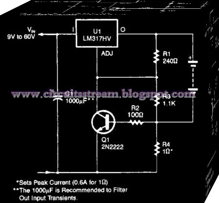
This is the Simple Current-Limited 6-V Charger Circuit Diagram. An LM317HV regulator is used as a current-limited charger. If current through R4 exceeds 0.6 A, Ql is biased on which pulls the ADJ terminal of the LM317 HV to ground and reduces the battery-charging current. 

 Simple Current-Limited 6-V Charger Circuit Diagram


 simple current-limited 6-v charger circuit diagram

Blinking LED Wiring diagram Schematic


This is a blinking LED schema diagram.Here I have used common IC NE555.If you want to change the speed of this schema you can change the value of R2.Then you can do that.


Note

* Use a PCB to build this schema
* You can operate this schema with 9V

Monday, August 25, 2014

Discrete Sliding Tone Frequency Ramp Doorbell

This Discrete Sliding Tone (Frequency Ramp) Doorbell schema produces a low tone that will slide up to higher frequency. The equivalent total resistance connected between the base of Q1 and ground (Rbg) , and coupling capacitor  C1  determines the AF oscillator’s frequency. The resistance (Rbg) is equal to (R2+R1)R3.  

Here is the schematic diagram of the schema. The R2 is used to set the initial bias condition, adjusted to produce a pleasant low starting frequency doorbell tone. D1 will start to conduct when Capacitor C3 charge through R6 until it reaches D1 bias  voltage level. 

Then the value of Rbg is paralleled by R4 and D1, and R5-D2-D3, and the values of diode’s equivalent resistance is gradually decreased as the C3 voltage ramp up.  This decreasing resistance value make the output tone slides up in frequency.  Two different diode path is provided to extend the linear area of diode conduction transition slope. With two path with different biases, after the single diode path has saturated, the second path provide further linear increase at higher voltage level.

 Discrete Sliding Tone (Frequency Ramp) Doorbell Circuit

Discrete

Universal PIC Programmer Circuit

Universal
The series of Universal PIC Programmer can be used with software IC-Prog 1:05. Universal PIC programmer circuit is very simple with BC337 transistor 1 fruit, 2 pieces of IC regulators 7805 and 7808 as well as supporting passive components. Universal PIC Programmer series can be supplied with 2 pieces of 9V batteries.
Read more

Simple Siren Alarm Wiring diagram Schematic

We need security systems alarms for home companies and etc . This is a Simple Siren Alarm Circuit Diagram . This schema use in car and other places . The ramp voltage from the low frequency oscillator 1C1 modulates IC2 thereby producing a rising and falling tone like the siren wail of police cars.

Simple Siren Alarm Circuit Diagram

Simple

Versatile DC DC Converter

Here is a versatile power coupler that connects a device to 5V-19V DC generated from AC mains by a power adaptor. Power adaptors come in different voltage outputs like 5V (for mobile phones), 12V (for external hard drives) and 19V (for laptops). Sometimes the power adaptor may have a voltage rating higher than the required voltage. With the converter schema given here, the adaptor can be used to power any device at a lower voltage. 

For instance, by using a 19V laptop adaptor, you can power a TTL schema at 5V. There can also be other instances when one needs a 3V or 6V supply. All these and many other intermediate voltages are easily possible with this versatile converter schema when used together with any off-hand power adaptor.


Versatile
Versatile DC-DC Converter Circuit diagram

Fig. 1 shows the schema of the DC-DC converter. Smooth reduction in the voltage is achieved using the LM317 regulator IC. The complete unit can fit inside a piece of a glue stick tube.
Adjusting variable resistor VR1 gives the desired output voltage. The output voltage is read using a 0-100µA ammeter, whose series resistance R* is chosen such that the maximum desired voltage could be covered. For instance, if full-scale deflection (FSD) current of the meter is 100 µA and you need an output voltage of up to 15V, then R* = 15/0.0001 = 150 kΩ. The desired value of R* is obtained by using 150-kilo-ohm preset VR2. 

Use of a variable resistor which also has an on/off switch like the one in old radios is recommended. It will cut off the coupler from the input power supply without having to accomodate an additional switch. Also, use a heat-sink with LM317 to handle the desired amount of power.

Proposed-assembly

Assemble the schema on a small general-purpose PCB and enclose in a suitable case. Fit the entire PCB inside a glue stick tube as shown in Fig. 2. Affix the female and male connectors on the opposite ends and place the ammeter in between the stick tube. You can directly read the output voltage on the ammeter after due calibration.

Note. You can use a suitable VU meter instead of 0-100µA ammeter and calibrate accordingly.

Copyright : EFY

Sound Level Meter


This is a wonderful schema which gives an attraction for your amp or audio setup so after fixing correctly you will be able to get maximum harvest of it.


Parts List.

Q1 BC 558 PNP Transistor
LED1-LED10 Standard LED or LED Array
R1, R3 1K 1/4W Resistor
R2 10K 1/4W Resistor
R4 100K 1/4W Resistor
R5 1M 1/4W Resistor
D1 1N4001 Silicon Diode
U1 LM3915 Audio Level IC
MISC Board, Wire, Socket For U1
C1 2.2uF 25V Electrolytic Capacitor
C2, C3 0.1uF Ceramic Disc Capacitor

Sunday, August 24, 2014

14 14W STEREO AMPLIFIER WITH MUTE ST BY

Features

WIDE SUPPLY VOLTAGE RANGE UP TO
±20V
SPLIT SUPPLY
HIGH OUTPUT POWER
14 + 14W @ THD =10%, RL = 8Ω, VS = +16V
NO POP AT TURN-ON/OFF
MUTE (POP FREE)
STAND-BY FEATURE (LOW Iq)
SHORT CIRCUIT PROTECTION TO GND
THERMAL OVERLOAD PROTECTION

Circuit Diagram:
Circuit diagram for 14 + 14W STEREO AMPLIFIER WITH MUTE & ST-BY


Homemade Fence Charger Energizer Circuit Explained

The electric fence charger schema presented here is basically a high voltage pulse generator. The super high voltage is derived from a commonly used automobile ignition coil. An a stable multivibrator is used to generate the required frequency to drive the ignition coil. Another a stable is used to control the pulses supplied to the fence.

 If you have large agricultural fields and desperately need to protect the crops from uninvited guests like animals and possibly humans, then this electric fence charger device is just what you are looking for. Build and install it yourself. An electric fence is an electrified high voltage barrier which produces painful shocks if physically touched or manipulated. Thus such fencing basically function as deterrents for animals as well as human intruders and stop them from crossing the restricted boundary.

Build

Build


The present schema of an electric fence charger is designed and tested by me and has proved sufficiently powerful for the application. The schema is able to produce voltage pulses up to 20,000 volts, needless to say about the fatality rate involved with it. However the pulses being intermittent, provides the subject with enough time to realize, recover and eject.

The generated pulse is so powerful that it can easily arc and fly-off between short distances of around a cm. so the fencing conductor needs to be separated adequately to avoid leakages through arcing and sparking. If not tackled, may drastically reduce the effectiveness of the unit.

Here the generation of high voltage is primarily carried out by an automobile ignition coil.

The winding ratios of an ignition coil are specifically designed and intended for creating high voltage arc between a two closely spaced conductors inside the ignition chamber to initiate the ignition process in vehicles.

Basically it’s just a step-up transformer, which is able to step-up an input applied voltage at its primary winding to monstrous levels at its output or the secondary winding.

SOME POINTS OF THE CIRCUIT AND THE IGNITION COIL IS VERY DANGEROUS TO TOUCH WHEN POWERED. ESPECIALLY THE IGNITION COIL OUTPUT IS TOO LETHAL AND MAY EVEN CAUSE PARALYSIS.

Let’s diagnose the whole thing more deeply.

Circuit Description


In the CIRCUIT DIAGRAMwe see that the entire schema is basically comprised of four stages.

A DC oscillator stage, An intermediate 12 to 230 volts step-up stage, The voltage collector and firing stage and The super high voltage-booster stage.

 TR1 and TR2 are two normal step-down transformers whose secondary windings are connected through SCR2. TR2’s input primary winding may be selected as per the country specification.

However, TR1’s primary should be rated at 230 volts.

IC1 along with the associated components forms a normal astable multivibrator stage. The supply voltage to the schema is derived from the secondary of TR2 itself.

The output from the astable is used to trigger SCR2 and the whole system, at a particular fixed intermittent rate as per the settings of P1.

During the ON periods, SCR2 connects the 12 volt AC from TR2 to the secondary of TR1 so that a 230 volt potential instantly becomes available at the other end of TR1.

 This voltage is fed to the voltage-firing stage consisting of the SCR1 as the main active component along with a few diodes, resistor and the capacitor C4.

The fired voltage from SCR1 is dumped into the primary winding of the ignition coil, where it is instantly pulled to a massive 20,000 volts at its secondary winding. This voltage may be suitably terminated into the fencing.

The high voltage generated by this electric fence charger will need to be carefully applied across the whole length of the fence.

The two poles from the ignition coil connected to the fence wiring should be kept at least 2 inches apart.

The pillars of the fence should be ideally made of plastic or similar non conducting material, never use metal and not even wood (wood tend to absorb moisture and may give path to leakages).

 Parts List

R4 = 1K, 1WATT,
R5 = 100 OHMS, 1WATT,
P1 = 27K PRESET
C4 = 105/400V PPC,
ALL DIODES ARE 1N4007,
IC = 555
TR1 = 0-12V/3Amp (120 or 230V)
TR2 = 0-12V/1Amp (120 or 230V)
BOTH THE SCRs ARE C106 OR PREFERABLY BT151,

TWO WHEELER IGNITION COIL IS SHOWN IN FLUORESCENT BLUE COLOR


Author Swagtam

Equalising HEXFETs

When experimenting with audio output stages featuring multiple HEXFETs it quickly becomes apparent that the total power is not divided equally among the individual transistors. The reason for this lies in the wide part-to-part variations in gate-source voltage, which in the case of the IRFP240 (or IRFP9240) can be from 2 V to 4 V. Source resistors in the region of 0.22 Ω as commonly seen in amplifier diagram (see example schema extract) help to counteract this, but usually not to a sufficient extent. One possible solution to this problem is to ‘select’ the transistors used so that their gate-source voltages match as closely as possible.


For building prototypes or very short production runs this is feasible, but requires additional manual effort in testing the components, and, of course, more transistors must be ordered than will finally be used. The schema idea shown here allows differences in gate-source voltage between pairs of transistors to be compensated for by the addition of trimmer potentiometers: the idea has been tested in simulation using Simetrix. The second schema extract shows the required changes.