Tuesday, September 2, 2014

Make your phone battery last longer

Make
 
Running out of battery at the most inconvenient moment is a situation that happens more often than we would like. The services currently offered multiple cell phones lead to a continuous drain on the battery, having often upload at the end of the day as if our smartphone need rest as much as us. To try to make the battery last us a bit more, we offer these tips:

1. The screen is ample, which consumes more energy on our phone. Therefore, avoid looking at every minute cell would be to start with the best advice. Adjust the screen brightness will also help us better power consumption. Likewise, it is advisable to reduce the consumption of games, watch videos, or even record and take pictures. All these applications have a high battery consumption, and if what we want is that last a little longer, we have to reduce the time spent on these activities.

2. Any service to determine our location, such as GPS, it should be disabled if not in use at that time. There are many services that use location for information about us and if we do not need, we will inadvertently limiting the life of our battery.

3. Optimize battery usage. Some phones include software specifically designed to optimize battery usage, so its a choice you make. If our model integrates not, we can always unburden an app to perform that function. There are many for all operating systems.

4. Having automatic updates enabled our favorite social networks, emails or any other tool, it will not help either. Because of the frequency with which updates are received, this is an unnecessary battery drain. Ideally disable this feature and manually check the applications when we agree.

5. Whenever we are in our home, at work, or have available a Wi-Fi, it is advisable to disconnect the data service and connect to the wi-fi. Our battery will thank us.

6. When we are connected to a wi-fi, we must use to update your operating system and various applications. Although it can be a bit cumbersome, especially OS upgrade, our phone will work more efficiently, as we most likely will include some improvement on the energy use of our device.

7. Heat is a great enemy of electronic devices. Avoid, as far as possible, the phone is exposed to extreme temperatures, especially heat, as it affects the life of the battery.

8. Finally, using these tricks even if you still have the feeling that your battery lasts very little, you can always buy an external battery that lets you use the phone a little longer.
Read More

2002 Chevrolet Chevy Impala Wiring Diagram

2002 Chevrolet Chevy Impala Wiring Diagram
This is 2002 Chevrolet Chevy Impala Wiring Diagram: power distribution, battery, ignition switch, junction block, crank relay, starter solenoid, relay ctrl, powertrain ctrl module, crank voltage, fusible link, generator,black wire,  solenoid contacts, yellow wire, schematics
Read More

Monday, September 1, 2014

NCP2890 Audio Amplifier 1W

NCP2890general description:

The NCP2890 is an audio power amplifier designed for portable communication device applications such as mobile phone applications. The NCP2890 is capable of delivering 1.0 W of continuous average power to an 8.0 BTL load from a 5.0 V power supply, and 320 mW to a 4.0 BTL load from a 2.6 V power supply. The NCP2890 provides high quality audio while requiring few external components and minimal power consumption. It features a low−power consumption shutdown mode, which is achieved by driving the SHUTDOWN pin with logic low. The NCP2890 contains circuitry to prevent from “pop and click” noise that would otherwise occur during turn−on and turn−off transitions. For maximum flexibility, the NCP2890 provides an externally controlled gain (with resistors), as well as an externally controlled turn−on time (with the bypass capacitor). Due to its excellent PSRR, it can be directly connected to the battery, saving the use of an LDO. This device is available in a 9−Pin Flip−Chip CSP (standard Tin−Lead and Lead−Free versions) and a Micro8 package. NCP2890 Audio Amplifier 1W

NCP2890 features:

  • 1.0 W to an 8.0  BTL Load from a 5.0 V Power Supply
  • Excellent PSRR: Direct Connection to the Battery
  • “Pop and Click” Noise Protection Circuit
  • Ultra Low Current Shutdown Mode
  • 2.2 V−5.5 V Operation
  • External Gain Configuration Capability
  • External Turn−on Time Configuration Capability
  • Up to 1.0 nF Capacitive Load Driving Capability
  • Thermal Overload Protection Circuitry
  • AEC−Q100 Qualified Part Available
  • Pb−Free Packages are Available
  • NCV Prefix for Automotive and Other Applications Requiring Site and Control Changes

NCP2890 aplications:

  • Portable Electronic Devices
  • PDAs
  • Wireless Phones

NCP2890 circuit diagram: 

NCP2890 layout pcb: 


Read More

60W ICs amplifier with OM961

Amplifier circuit is very suitable for use in car audio speakers that use a subwoofer, with a power output of about 60W and impedance of 4 Ohm. Supply voltage ranging from 12V to 35 volts with currents +, -, and ground. If using battery then use 12V DC to DC converter which produces 3 voltage +, -, and ground.
60Watt

Component List :
Resistor
R1 = 10K
R2 = 4K7
R3 = 10R
R4 = 2.2R
R5 = 10R
R6 = 10K
R7 = 680R
R8 = 300R
Capacitor
C1 = 1uF
C3 = 10uF
C4 = 10uF
C5 = 470uF
C6 = 0.1uF
C7 = 100uF
C8 = 120pF
C9 = 270pF
C10 = 47uF
IC = OM931 , OM961
Read More

Pre regulated High Voltage Power Supply Wiring diagram Schematic

This Pre-regulated High Voltage Power Supply Circuit Diagram triacs selects the tap on main transformer Tl, which provides the proper, pre-regulated voltage to the secondary regulator. T2 and its associated components comprise the secondary regulator. The ADC 0804, IC1, digitizes a voltage-feedback signal from the secondary regulator`s output. 

 Pre-regulated High Voltage Power Supply Circuit Diagram

Pre-regulated


The MC1415 De-multiplexer, IC2, decodes the digitizer`s output. IC2, in turn, drives Tl`s opto-isolated triacs via the 74LS240 driver chip, IC3, and associated opto-isolators. Transformer T3 samples the schema`s current output. The auxiliary, 12 V winding on Tl ensures noload starting. The combination of op amp IC5 and the inverting transistor, Ql, square this current signal. 

The output of Ql is the CLK signal, which triggers one-half of the one shot, IC4A, to begin the schema`s AID conversion. The one shots` periods are set to time out within 1l2 cycle of the ac input. Upon completion of its AID conversion, ICl`s INTR output triggers the other half of the one shot, IC4B, which enables the converter`s data outputs. The rising edge of the CLK signal resets the one shot and latches the new conversion value into IC2. The latch, associated driver, and optoisolator trigger a selected triac according to the latest value of the voltage-feedback signal, V, . Keep enjoying dont forget click on share button .


Read More

Light to Frequency converter circuit


Here is the schema diagram of a effective light to frequency converter schema that can be used for variety of applications such as light intensity measurement,fun etc.


The schema is based on TLC555, the CMOS version of famous timer IC NE 555. A photo diode is used for sensing the ligt intensity.The timer IC is wired in astable mode.The leakage current of the reverse biased photo diode is proportional to the light intensity falling on it.This leakage current charges the capacitance C1.When the capacitor voltage reaches 2/3 of the supply voltage the out put (pin 3) goes low.As a result the capacitor discharges through photo diode .When the capacitor voltage reaches 1/3 the supply voltage the out put (pin 3) of IC goes high.This cycling continues and we get a frequency at pin 3 proportional to the light intensity falling on the photo diode.


Notes.

* With the given components the frequency varies from 1KHZ @ complete darkness to 24 Khz @ bright sunlight.The frequency range can be changed by using different values for C1.

* Use any general purpose photo diode for D1.

Read More

Electronic Touch Switch 1 Wiring diagram Schematic

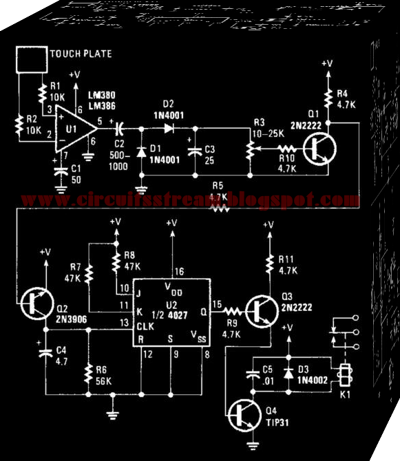
This is an Electronic Touch Switch 1 Circuit Diagram. This switch reacts to the touch of a finger to turn lights and/or appliances on or off. The device uses the human body as an antenna to pick up 60-Hz hum, which is applied to a metal plate by your finger. The signal is fed to the input of Ul, an LM380 audio-power amplifier. An LM386 should work as well. 
 

 Electronic Touch Switch 1 Circuit Diagram


 electronic touch switch 1 circuit diagram
 
The 60-Hz output from the amplifier is rectified by Dl and D2, then filtered by C3. Potentiometer R3 sets the trigger voltage used to saturate Ql. When Ql turns on, the collector end of R4 goes almost to ground and provides the needed voltage to turn on Q2. Transistor Q2 turns on and clocks. 
 
The flip-flop is configured for toggle-mode operation, so its output switches states with each clock pulse. The 4027 (U2) is wired to toggle by tying the J and inputs high and the set and resets low. Transistor Q3 is connected to the Q output through the 4.7-KOhmhm resistor. Transistor Q3 drives Q4, the relay driver. Be sure that the load does not exceed the relay ratings.
Read More