Showing posts with label v. Show all posts

Friday, November 7, 2014

Simple 9 V Battery Replacement

This circuit was originally designed to power a motorcycle intercom from the vehicle supply system. This type of intercom, which is used for communication between driver and passenger, generally requires quite a bit of power. In order to improve intelligibility there is often elaborate filtering and a compander is sometimes used as well. The disadvantage is that a battery doesn’t last very long. You could use rechargeable batteries, of course, but that is often rather laborious. It seems much more obvious to use the motorcycle power supply instead. 

9-V Battery Replacement Circuit Diagram
A 9-V converter for such an application has to meet a few special requirements. For one, it has to prevent interference from, for example, the ignition system reaching the attached circuit. It is also preferable that the entire circuit fits in the 9-V battery compartment. This circuit meets these requirements quite successfully and the design has nonetheless remained fairly simple. In the schematic we can recognise a filter, followed by a voltage regulator and a voltage indicator. D1, which protects the circuit against reverse polarity, is followed by an LC and an RC filter (C3/L1/L2/C1/R1/C2). This filter excludes various disturbances from the motorcycle power system. Moreover, the design with the 78L08 and D3 ensures that the voltage regulator is operating in the linear region. The nominal sys-tem voltage of 14 V can some-times sag to about 12 V when heavy loads such as the lights are switched on. 

Although the circuit is obviously suitable for all kinds of applications, we would like to mention that it has been extensively tested on a Yamaha TRX850. These tests show that the converter functions very well and that the interference suppression is excellent.
Read More

Wednesday, November 5, 2014

Ground free DVM Module Supply from 5 V

The majority of hand-held digital volt meters use an LCD screen and are powered from a nine volt battery. Inside is most probably an ICL7106 chip (or something compatible). This takes care of measuring the input and driving the LCD. This IC is very popular and can be found in other laboratory and homebrew equipment where it offers a simple solution for both measuring current/voltage and driving the display.

So far so good, there is how-ever one feature of this device which needs careful consideration. The power supply to the chip (both the positive and negative connection) must not have any direct connection to either of the two measuring input terminals. It requires floating supplies. This is not a problem for battery powered equipment but needs more thought when the ICL7106 is fitted into mains powered equipment.

Ground-free DVM Module Supply from 5 V Circuit Diagram :

Ground-free

The simplest, most expensive solution is to use two independent power supplies in the equipment. A battery could also be used as an isolated supply but in a mains powered device it would seem a bit out of place and inconvenient.

In this case the term ‘floating supplies’ means that it is possible to have two separate DC levels. This level of isolation can be achieved with capacitors to separate the two DC supplies. Back in 2003 we published a circuit in the July/August edition of Elektor (circuit number 75) which used a NE555 IC. Unfortunately this design required a supply voltage upwards of 10 V. If the DVM module is fitted to equipment which only uses a 5 V supply (as is often the case) the circuit will not be of much use.The author has solved the problem by modifying the original circuit, using a hex Schmitt trigger inverter type 74HC14N instead of the NE555. One of the inverters generates a square wave of about 75 KHz. The remaining five inverters are wired in parallel to pro-vide more output drive current for the voltage multiplier stage.

DC isolation is provided by capacitors C2 and C3. A classic voltage multiplier configuration is made up of capacitors and diodes. The circuit generates an output of around 8.5 V at a load current of 1 mA. This is sufficient to power the DVM chip. The 5 V supply for the circuit must be stabilised.

The values of the input voltage divider resistors R2 and R3 are independent of the chip’s power supply and must be selected according to the desired measurement range.


Read More

Saturday, September 6, 2014

9 V Battery Replacement Wiring diagram Schematic

This schema was originally designed to power a motorcycle intercom from the vehicle supply system. This type of intercom, which is used for communication between driver and passenger, generally requires quite a bit of power. In order to improve intelligibility there is often elaborate filtering and a compander is sometimes used as well. The disadvantage is that a battery doesn’t last very long. You could use rechargeable batteries, of course, but that is often rather laborious. It seems much more obvious to use the motorcycle power supply instead. 

9-V Battery Replacement Circuit Diagram


Power-Supply-Circuit-Diagram

A 9-V converter for such an application has to meet a few special requirements. For one, it has to prevent interference from, for example, the ignition system reaching the attached schema. It is also preferable that the entire schema fits in the 9-V battery compartment. This schema meets these requirements quite successfully and the design has nonetheless remained fairly simple. In the schematic we can recognise a filter, followed by a voltage regulator and a voltage indicator. D1, which protects the schema against reverse polarity, is followed by an LC and an RC filter (C3/L1/L2/C1/R1/C2). This filter excludes various disturbances from the motorcycle power system. Moreover, the design with the 78L08 and D3 ensures that the voltage regulator is operating in the linear region. The nominal sys-tem voltage of 14 V can some-times sag to about 12 V when heavy loads such as the lights are switched on. 

Although the schema is obviously suitable for all kinds of applications, we would like to mention that it has been extensively tested on a Yamaha TRX850. These tests show that the converter functions very well and that the interference suppression is excellent. 
Read More

Tuesday, August 26, 2014

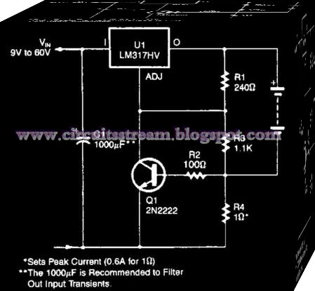
Simple Current Limited 6 V Charger Wiring diagram Schematic

This is the Simple Current-Limited 6-V Charger Circuit Diagram. An LM317HV regulator is used as a current-limited charger. If current through R4 exceeds 0.6 A, Ql is biased on which pulls the ADJ terminal of the LM317 HV to ground and reduces the battery-charging current. 

 Simple Current-Limited 6-V Charger Circuit Diagram


 simple current-limited 6-v charger circuit diagram
Read More