Showing posts with label current. Show all posts

Sunday, October 5, 2014

Increasing Regulator Current PSU Circuit


Description:
An outboard pass transistor used to increase the current output of a voltage regulator IC.

Notes
Although the 78xx series of voltage regulators are available with different current outputs, you can boost the available current output with this circuit. A power transistor is used to supply extra current to the load the regulator, maintaining a constant voltage. This transistor is known as an outboard bypass transistor.

Currents below 600mA will flow through the regulator. Above 600mA the input current flowing through the 1 ohm resistor develops a voltage. As this voltage increases above 0.6V (600mA through 1 ohm) then the TIP2955 power transistor starts to conduct, supplying the extra current to the load. The 10 ohm resistor limits excessive base current. The power transistor requires an adequate heat sink as it is likely to get very hot. Suppose you use a 12v regulator, 7812. The minimum input voltage should always be a few volts higher than the regulator output voltage to allow for voltage drops.

The 1 ohm resistor needs to be rated 3 Watts for load currents up to 3 amp and rated 7 Watts for load currents of 5 amps. As the HFE of a power transistor falls with increased collector current it is not recommended to draw more than 5 amps with this circuit. The 10 ohm base resistor drops less power and a 0.5 Watt resistor can be used at all output currents.

Power Dissipation in Bypass Transistor
Assume a supply of 20 volts and that the load will draw 5amps. The power dissipation in the transistor will be Vce * Ic.
Vce = Vcc - Vreg
so
Pdiss = (20-12) * 5 = 40 Watt.

It may keep you warm in the Winter, but you will need a large heatsink with good thermal dissipation. If however the input voltage was 15V then the dissipation would be reduced to just 15 Watts. If you want to increase the output current with a negative regulator, such as the 79xx series, then the circuit is similar, but an NPN type power transistor is used instead.
Read More

Thursday, October 2, 2014

Constant Current LED Driver Circuit

 If an LED is used in a circuit, the current for that LED is normally set with a limiting resistor. The LED can then be switched on and off by means of a transistor.
The following discussions explains a transistor based configuration which ensures a constant current drive to the conected LEDs, under  all circumstance.

However, the method shown in figure l does not take into account any variations in the supply voltage. A small variation in the LED current can be very conspicuous especially when high efficiency LEDs are used. The addition of just one transistor can transform the circuit of figure 1 to a onstant current source which can be switched on an off (for instance, with TTL levels). The circuit of figure 2 shows that resistor R1 has been moved to the emitter of T1. When a drive voltage is applied to the input of T1, this transistor conducts which causes a current through R1. Transistor T2 controls the base current of T1 such that I the voltage drop across R1 remains at 0.6 V. The current, l, through the LEDs and R1 is calculated by l= 0.6/R1. lf, for instance, R1 is 12 S2, the current through the LEDs is 50 mA. Bear in mind that the dissipation of T1 is somewhat higher than in the circuit of figure 1, but against that, the dissipation in R1 is not as high.
Read More

Sunday, September 21, 2014

Amplifier current negative feedback TDA7294 DC Servo

TDA7294

In the field of consumer reports electronics products reviews, product size, weight is toward smaller, lighter direction, high-power single-chip audio power amplifier needs of increasingly prominent, TDA7294 is currently the best performance, the biggest single-chip audio power amplifier One.

It consists of the European SGS-THOMSON Italian-French company in accordance with discrete components A and B audio amplifier circuit design from classic. Its former low-level noise, low distortion of the bipolar transistor circuit, at the end of a high-pressure, high current DMOS output of the buffer, it has bipolar circuit sounds pure merit, have large current high voltage FET Driver output characteristics.

Since 1998 TDA7294 introduced to China so far, I believe that many enthusiasts have been TDA7294 delicate taste, natural sound. Regrettably, however, is that they have heard only negative feedback is standard voltage of the voice amplifier.

And negative feedback amplifier voltage than current negative feedback amplifier as excellent transient nonlinear distortion and intermodulation distortion characteristics, the frequency amplifier curve flat, high and low frequency response more exhibition wide; more important is that circuit Will load impedance into the feedback network, it can change the speakers of such fierce resistance to the load compensation, coupled with stable and reliable performance, than the negative feedback voltage amplifier has more advantages, the current negative feedback current amplifier is widely For the modern high-fidelity audio amplifier.

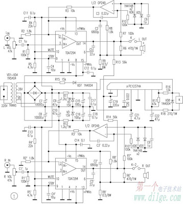
Figure 1 circuit is an excellent performance, improve the design of the fever-100 W × 2 DC Servo Amplifier current negative feedback stereo amplifier, formed by the two TDA7294, the frequency response of 10 Hz ~ 100kHz. The use of sophisticated audio Yun-double as the two-channel amplifier DC Servo Amplifier output. Speakers from the protection of ASIC μPC1237HA driver completed the relay switch-mute and amplifier output DC offset protection, and other speakers. When the AC power plug, the relay will be delayed for some time speakers access amplifier; disconnecting the AC power when, μPC1237HA detected exchange loss, immediately disconnect the speaker to relay, the amplifier is the complete elimination of the set, Shutting down the transition process the impact of noise on the speakers.

In actual use, taking into account the electricity grid fluctuations Rectifier amplifier output voltage ± Vs volatile, in order to avoid over-voltage and high temperature in the state of damage TDA7294 (Note pressure in the temperature of 25 under the conditions, if the temperature exceeds 25 , TDA7294 the value will subsequently reduce the pressure), the exchange recommended power supply voltage transformer CT-AC26V × 2.

Listen:

Speaker to use B & W601, CD machine Marantz CD-19, compared TDA7294 amplifier for the negative feedback standard voltage lines. Software programs at Cai Qin, "the film" test the human voice, Mutebutsi trial String, RRs "Tutti" dynamic test, Rubinstein "Chopin Nocturne" trial piano.

The results are as follows:

In a dynamic sense of speed, the two amplifier very close, but the sound on the current negative feedback is obviously more sweet; the string, the human voice like the rendering software for a warmer, the details of the re-orientation; due to current negative feedback circuit Impedance of the compensation, the low-band high-impedance output has been strengthened, so dive in the low-frequency and intensity of the depth occupied obvious advantage.

Current negative feedback in addition to direct stereo amplifier for CD, VCD, DVD, and other music source amplifier, but also with audio processing unit for use by different combinations of the playback effect.

Read More

Wednesday, September 10, 2014

5V High Current Regulated Circuit

5V High Current Regulated Circuit

Since the accession of the 3-pin regulator ICs in the market, the affair of designing ability accumulation diagram has become beneath and beneath discussed. However, the aforementioned new ICs absolute the types of ability diagram actuality congenital in amusement labs to about 1 ampere units. In addition, ability stages are required, because aerial accepted (5A or 10A) voltage regulator ICs are actual expensive. This is the capital acumen why hobbyists usually opt for a detached solution. The abstraction of cascaded ability stages are absolutely not that bad. For this reason, we accept acclimated detached apparatus for the ambit featured above.

This regulator ambit was advised for microcomputer systems and added applications that crave beating aggressive ability accumulation while carrying aerial accepted achievement at the aforementioned time. The 723 IC acclimated in this architecture is broadly replaced by the new 3-pin regulators. However, the 723 IC is adjustable and its abstruse abstracts are bigger in some points. It is configured in the ambit to achievement voltage levels from 2V to 7V. The bare ability is produced by acceleration the voltage akin through a voltage doubler schema, afterlight it, and acclimation it with a 3-pin regulator IC.

This acutely complicated address is actuality activated actuality to accumulate the voltage akin as low as accessible at the accessory ambagious of the transformer. This makes it accessible to accumulate the ability amusement at transistors T1 and T2 as low as accessible too.

The calefaction bore for T1, T2 and T3 charge be appropriately dimensioned. A calefaction attrition of about 2�C (C F) is recommended. For the aforementioned reason, the resistor ethics for R1, R2 and R2 charge be produced by base resistors in parallel. For R1 and R2: affix two 0.33 ohms (5watts) in alongside for each. For R6: affix two 0.22 ohms (5watts) in alongside by a accepted achievement of 6 amperes; or affix three 0.22 ohms (5watts) in alongside by an accepted achievement of 8 amperes. As added assurance measure, adhesive these resistors on the pcb with some ambit from the board.

If one desires to abolish the voltage doubling, aloof abolish the apparatus D1, D3, C3, C4 and move the diode D2 to the absolute DC band as apparent by the dotted band in the Diagram 1.0. Additionally, the achievement voltage of the agent charge be added , and the ethics of C1, C2, R4 and R5 adapted appropriately.

This ability supply�s voltage achievement drops, by a amount of 0.85 ohms, from 5.5 volts to 5.32 volts. That after-effects to a accepted achievement of about 8 amperes! The voltage bead is aloof 3.3%! The ripple DC voltage is alone beneath than 28 mVeff at the output.

Read More

Tuesday, August 26, 2014

Simple Current Limited 6 V Charger Wiring diagram Schematic

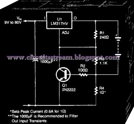
This is the Simple Current-Limited 6-V Charger Circuit Diagram. An LM317HV regulator is used as a current-limited charger. If current through R4 exceeds 0.6 A, Ql is biased on which pulls the ADJ terminal of the LM317 HV to ground and reduces the battery-charging current. 

 Simple Current-Limited 6-V Charger Circuit Diagram


 simple current-limited 6-v charger circuit diagram
Read More