Monday, January 26, 2015

DC Coupled Audio Amplifier

Designs for audio amplifiers with DC coupling to the load are not often encountered these days, even though they offer definite advantages. One advantage is that there is no need for the complication of a second (symmetric) power supply; another is good frequency and phase response. Also, no special electrolytic capacitors are needed for voltage stabilisation, and switch-on ‘thump’ is much reduced. To try to rescue this class of circuit from obscurity the author has designed a headphone amplifier working along the lines illustrated in Figure 1.

DC-Coupled Audio Amplifier Circuit Diagram


It consists of a voltage divider, a voltage follower and the loudspeaker in the headphones, whose other side is connected to the junction of two electrolytic capacitors, providing the virtual earth. The potential at this point is, of course, half the supply voltage. All we need to do now is suitably couple in the audio signal to be amplified. Figure 2 shows a practical realisation of this idea in the form of a stereo headphone amplifier. The amplifier itself consists of IC1 and P1, R3 and R4 (giving a gain of 11).

DC Coupled Audio Amplifier Circuit Diagram


This part of the circuit demands no further explanation, and the same goes for the voltage divider mentioned above, formed by R1a and R1b. The signal is coupled in via the potentiometers. C2 and R2 have a special purpose: C2 connects the bottom end of the potentiometers (ground for the input signal) to the virtual earth. However, this capacitor creates a feedback path which can lead to oscillation of the amplifier under some circumstances. R2 damps this tendency to oscillate.
 
It is possible to calculate suitable values for these components, but it is better to determine them by experiment. C2 must be sufficiently large that stray electric fields do not cause unacceptable hum at the output. R2 must be sufficiently large that the voltage at the amplifier’s virtual earth stabilises quickly enough after switch-on. The polarity of the electrolytic is unimportant as no significant voltage appears across the network. It is possible to try the circuit out with the C2/R2 network shorted and observe the behaviour of the circuit at switch-on using an oscilloscope. Depending on the degree of asymmetry in the circuit, the voltage at the virtual earth point can take a considerable time to stabilise.


Read More

Tuesday, January 6, 2015

Audio Stereo Power Amp Circuit

audio-power-amp-schematic

This is a 50 Watt Audio power amplifier circuit based single IC STK4036II. Use heatsink to prevent overheating on the IC. 

The amplifier circuit will give you good quality of sound unexpensive and have low price. 

It is easy we make a power amplifier using only few external components. 

The STK4036II amplifier are will find in enough eponymous stereo amplifiers , but also in enough activety loudspeakers. 
Read More

Friday, December 12, 2014

Phone ringtone generator circuit


ringtone-generator-schematic
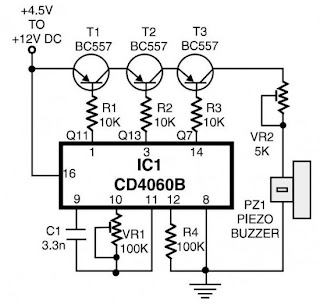
This is a simple home telephone ringtone generator circuit which is built with applying only several electronic components / parts.It generates simulated telephone ringtone and requires only DC supply with 4.5V DC to 12V DC voltage.One may possibly use this circuit in ordinary intercom or phone-type intercom. 

The sound is pretty loud when this circuit is operated on +12V DC power supply. Even so, the volume of ring sound can be adjusted.
Read More

Battery Indicator schematic diagram


This circuit diagramc shows a simple battery level indicator.In general, in mobile phones, the battery levels is displayed in dot or bar style.This helps you to effortlessly acknowledge the battery level.
Read More

6 Input Mixer


mixer-6-input
 
A simple mixer with 3 line inputs and 3 mic inputs using commonly available parts. 
Read More

Rain Detector schematic

Here's a simple rain detector circuit. It uses a sensor made of a small piece of etched PC board and a simple SCR circuit to detect rain and sound a buzzer. The SCR could also be used to activate a relay, turn on a lamp, or send a signal to a security system.
Read More

Lead Acid Battery Charger

Except for use as a normal Batter Charger, this circuit is perfect to 'constant-charge' a 12-Volt Lead-Acid Battery, like the one in your flight box, and keep it in optimum charged condition. This circuit is not recommended for GEL-TYPE batteries since it draws to much current. The above circuit is a precision voltage source, and contains a temperature sensor with a negative temperature coëficient. 
Read More

Thursday, December 11, 2014

Variable Power Supply Circuit

0-28v
This is the schematic diagram of variable power supply.The output voltage of this power supply circuit can be adjust from 0V to 28V DC, while the current output is static the rang is about 6A up to 8A.
Read More

AC to DC Schematic

  1. Classic Plus and Minus DC Power Supply - produces both a positive 15v and a negative 15v from a 20vac wall adapter.
  2. AC to DC Boost Converter with PFC - Implementation of a AC to DC Boost Converter with power factor correction.
  3. Classic Linear 5v Supply Using 6.3vac Transformer - Circuit consists of an iron core transformer, a bridge rectifier, a filter capacitor and a voltage regulator.
  4. AC-to-DC converter circuit utilizing IGBTs - AC-to-DC converter furnishing a regulated DC-output voltage from an AC-input supply voltage
  5. Non-isolated Off-line AC to DC Power Supply - Efficient circuit can provide up to 100ma of a regulated 5 volts from an AC power.
Read More

Thursday, November 20, 2014

High Impedance amplifier circuits

Mini High Impedance Amplifier is an amplifier with 1 Watt and have a very high input impedance. The series amplifiers can have a very high input impedance because the use of two transistors in the input that is placed Darlington. Input impedance circuit amplifier achieves 20M Ohm. Mini High Impedance Amplifier circuit uses four transistors and an IC 741. Gain amplifier with high input impedance , we can provide the input signal from device with weak levels though.

High

Mini High impedance amplifier circuit is very cheap to make and quite simple. This amplifier circuit use 9VDC power supply.
Read More

Flash Lights with HT2014L

This scheme is almost the same with a flash light with LM3909. In this scheme only requires IC HT2014L as a leader, and a resistor and LED. For voltage here need ration power around 4.5 V. You can apply this series to a wider scale in comparing the use IC LM3909. For the scheme are below:

flash
Read More

Phone Ring Generator Using Switching Supply

PhonePhone Ring Generator Using Switching Supply Circuit

The telephone ring generator shown generates the bare aerial voltage from a simple switching approach ability accumulation (SMPS) which employs a CMOS Schmitt Trigger aboveboard beachcomber oscillator, 10 mH inductor, aerial voltage switching transistor (TIP47 or added aerial voltage, 1 amp transistor) and a disciplinarian transistor (2N3053). The inductor should accept a low DC attrition of 1.5 ohms or less. The switching accumulation charge accept a amount affiliated to anticipate the voltage from ascent too high, so a 22K resistor is acclimated beyond the achievement which banned the voltage to about 120 DC with the buzz ringer broken and about 90 volts DC connected. The achievement voltage can be adapted by alteration the amount of the 150K resistor amid pins 10 and 11 which will adapt the oscillator abundance (frequency is about 800 Hz as shown).

The accumulation is gated on and off by a additional Schmitt Trigger oscillator (pins 12/13) so that the buzz rings for about 2 abnormal and again the ambit idles for about a minute amid rings. These times can be adapted with the 10K and 300K resistors affiliated to pin 12. The advance button apparent is acclimated to manually arena the phone. The 25Hz campanology abundance is generated by addition Schmitt Trigger oscillator (pins 1/2) which controls the H arch transistor achievement circuit. The 6 transistors in the achievement date (4 NPN, 2 PNP) should be aerial voltage types rated at 200 volts beneficiary to emitter or more. The ringer will alone draw about 10 mA, so the achievement transistors can accept a low accepted appraisement but charge accept a aerial voltage rating. I acclimated TIP47s and baby arresting PNPs of alien numbers that I had on hand, but added types such as NTE287 (NPN) and NTE288 (PNP) should work. Both accept a 300 volt C-E appraisement and amount about $0.95 from mail adjustment houses.

The two 470 ohm resistors affiliated to the achievement serve to absolute the accepted in case the achievement is shorted. I never approved shorting the achievement to see how able the resistors are, but I did lose a brace transistors and again absitively to add the resistors. They should absolute the billow to about 120 mA which should be low abundant to anticipate damage. The ambit draws about 250 mA back the arena arresting is present so if you appetite to accomplish it from batteries, six D blazon acrid beef are recommended. It apparently wont assignment with a baby 9 volt battery.

Read More

IC555 Tester Circuit Diagram


555 timer tester is a simple circuit that serves to test the condition of IC 555. 555 timer circuit tester, in principle, start the timer 555 in astable multivibrator mode. As an indicator of the status of the timer 555 good condition or damaged to use 2 pieces LED which will light up in a blink alternately when the timer 555 in good condition. And only one will turn on or off all the timer 555 when the condition is broken. 555 timer circuit tester is powered using 9 Volt DC voltage source.

How to use 555 timer tester is in conjuction with IC 555 to test the existing IC socket according to the order button. Then activate the power switch to begin testing the 555 timer ic. Then live we observe the LED indicators 2buah before, whether flashing alternately (good) or not blink or even die all (timer 555 damaged).
Read More

Wednesday, November 19, 2014

Rain Detector Circuit

Rain Detector Using 555 is a simple alarm that can be used to find out when rain was came. Rain Detector Using In principle this is an a stable multivibrator 555 which is prepared by IC555 with a sensor attached that can detect water. A stable multivibrator with the 555 is set in the audio frequency with a frequency of 1 KHz. Rain Detector circuit 555 can be supply with voltage source that is free enough from 5-15 VDC.


Circuit Rain Detector can be mounted on motorcycle, car or other object that we want to protect from rain. Water sensor used in the circuit  Rain Detector Using IC 555.  We can make with a PCB that we make the path as shown in the image above by using aluminum foil  board or insulator boards.
Read More

1 5V Amplified Ear Circuit Diagram

1.5V1.5V Amplified Ear Circuit Diagram

Device purpose:

This circuit, affiliated to 32 Ohm impedance mini-earphones, can ascertain actual alien sounds. Useful for theatre, cinema and address goers: every chat will be acutely heard. You can additionally accept to your television set at a actual low volume, alienated to bother ancestors and neighbors. Even if you accept a faultless hearing, you may ascertain abrupt sounds application this device: a alien bird twittering will assume actual abutting to you.

Circuit operation:

The affection of the ambit is a constant-volume ascendancy amplifier. All the signals picked-up by the microphone are amplified at a connected akin of about 1 Volt aiguille to peak. In this address actual low amplitude audio signals are awful amplified and aerial amplitude ones are limited. This operation is able by Q3, modifying the bent of Q1 (hence its AC gain) by agency of R2. A noteworthy affection of this ambit is 1.5V array operation. Typical accepted drawing: 7.5mA.

Notes:

  • Due to the constant-volume control, some users may consider P1 volume control unnecessary. In most cases it can be omitted, connecting C6 to C3. In this case use a SPST slider or toggle switch as SW1.
  • Please note the stereo output Jack socket (J1) connections: only the two inner connections are used, leaving open the external one. In this way the two earpieces are wired in series, allowing mono operation and optimum load impedance to Q4 (64 Ohm).
  • Using suitable miniature components, this circuit can be enclosed in a very small box, provided by a clip and hanged on ones clothes or slipped into a pocket.
  • Gary Pechon from Canada reported that the Amplified Ear is so sensitive that he can hear a whisper 7 meters across the room.
    He hooked a small relay coil to the input and was able to locate power lines in his wall. He was also able to hear the neighbors stereo perfectly: he could pick up the signals sent to the speaker voice coil through a plaster wall.
    Gary suggests that this circuit could make also a good electronic stethoscope.
Read More

Some Type of Resistors

Much types of Resistors, is the most commonly used of all electronic components. There are different types of resistors are available with their primary function is to limit the current through the electrical circuit and to lower the voltage. Resistors are "Passive Components", which does not
contain a source of strength / reinforcement, but only weaken or reduce the signal voltage there are past them. When used in circuits generated DC Drop Voltage terminal was measured in both legs.

Resistor produces a voltage drop when an electric current flowing through it in accordance with Ohms Law, with different values ​​on each of resistor produces different values ​​of currents or voltages. This is very useful in electronic circuitry to control or reduce both current and voltage generated after flowing through it.

There are different type of resistors and manufactured in various forms because of certain characteristics and accuracy in accordance with the specific application fields, such as the High Stability, High Voltage, High Current, etc., or used as general purpose resistors where their characteristics are less of a problem. Some common characteristics associated with low resistor such as; Temperature Coefficient, Coefficient Voltage, Noise, Frequency Response, Power and Temperature Rating, Physical Size and Reliability.

On all Electrical and Electronic Resistors circuit illustrated with a line that "zig-zag" with the inclusion of the value in units of Ohms, Ω.

1. Carbon Composition Resistors - Made from carbon powder for low power / small watts.

Carbon Resistors is the Composite Resistors that most common for use in the use of any electronic circuit common and is considered the most expensive resistors. Its resistive element is made from a mixture of carbon powder or carbon graphite (like pencil leads) with ceramic (clay). The ratio of carbon to determine the overall value of resistive ceramic mixture and the higher this ratio the lower the resistance value. The mixture is then formed into a cylindrical shape and metal wire / conductor attached to each end, to provide electrical connections before the outside is coated with insulating material and color-coded signs.

Carbon Composite Resistors have a low to medium power with a low inductance which makes it ideal for high frequency applications, but has a weakness at the level of noise (high noise) and less stable in hot conditions. Identification of carbon composite resistors are prefixed with "CR" (eg CR10kΩ) and is available in Path E6 (± 20% tolerance), Panorama of E12 (± 10% tolerance) and the Panorama of E24 (± 5% & ± 2% tolerance) resistor type generally it has a power of 0.125 or 1 / 4 Watt to 2 Watt.

2. Metal Film Resistors or cermets resistors - Made of conductive metal oxide paste, for very low power

"Film Resistors" consists of Metal Film, Carbon Film and Metal Oxide Films, which is typically made ​​by depositing a pure metal coating, such as nickel, or oxide films, such as tin-oxide, the ceramic insulator rods or substrate. Resistive value of resistor is lowered by the thickness of the film were then given a helical groove by using laser light. This raises the effect of increasing the resistance because the conductive layer or a helical cut in the same result by wrapping the wire in coil form. This manufacturing method allows for the resistors of this type has a higher accuracy than the Carbon Resistor.

Metal Film Resistors have a much better temperature stability than carbon resistors are equal in size the level of noise / low noise and generally better for high frequency or radio frequency applications. Metal Oxide Resistors better capability in high waves with a much higher temperature capability than equivalent metal film resistors. Other types of film resistors is commonly known as the Thick Film Resistors made by superimposing a thicker conductive paste of ceramic and metal, called cermet, the alumina ceramic substrate. Such resistors are used in the manufacture of small electronic circuits such as in the manufacture of PCBs for Calculator, mobile phones and computer peripherals devices la. Has a temperature stability, low noise, and the proper voltage. Metal Film Resistors begins with the notation "MFR" (eg MFR100kΩ) and CF for Carbon Film types. Metal film resistors are available in the trajectory E24 (± 5% & ± 2% tolerance), E96 (± 1% tolerance) and E192 (± 0.5%, ± 0.25% & ± 0.1% tolerance) with the power of 0, 05 (1 / 20) Watt up to 1 / 2 Watt. In general, precision film resistors are low power components.

3. Wire Wound Resistors - With a metallic body as a heat absorbers, have a very high value of watts

Other types of resistors, wire wound resistors are called, are made by winding a thin wire metal alloy (Nichrome) or wire type of to ceramic insulators in the form of a spiral helix that is similar to Film Resistors. Resistors of this type are generally only available Ohm very low with high precision (from 0.01 to 100kΩ). These resistors are widely used in the instrument gauges on a Whetstone bridge circuit. This resistor also able to handle the electrical current is much higher than others with Ohm resistor the same value with a power rating of more than 300 Watts. Resistors of this type are called "Chassis Mounted Resistors". They are designed to be physically mounted on a heatsink or metal plate to further remove the heat generated thereby enhancing the ability of a current greater.

Wire wound resistor of this type begins with the notation "WH" or "W" (for example; WH10Ω) and are available in packs Aluminum Cladded (WH) with accuracy (± 1%, ± 2%, ± 5% & ± 10% tolerance) or the vitreous Enamelled W package (± 1%, ± 2% & ± 5% tolerance) with 1W power up to 300W or more

4. Semiconductor Resistors - Resistors for working at high frequency and precision.

Thats some type of resistors are widely used in everyday life, especially in the electronics field.
Read More

SAMSUNG protect circuit with LA76931

Following is the protect circuit Samsung TV which use IC LA76931 as basic working the protect circuit. This Protect Circuit LA76891 located at pin-30 whichconnected to the collector of transistor Q902.In normal conditions the voltage at the base of Q902 is "low" and the voltage at pin-30 is "high". For the temporary crippling protect, it can be removed Q902 (or to the emitter-base short).

SAMSUNG protect circuit with LA76931
Sampling circuit protect from:

Vertical Protect. Pulses of the vertical-out rectified by diode D355, so that the base voltage is approximately 0.6V Q904 ,and collector voltage is 0v.
X-ray Protect (option). Sampled using a heater voltage of the circuit as shown below. Normal vltage in x-ray path to the base of Q902 is zero.

ABL protect. If there is damage to flyback voltage which can cause a high rise ABL, then protect circuit will actively work.
Read More

Mosfet Amplifier with power output 400W

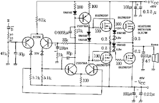
See figure below its power amplifier using transistor mosfet as amplifier.
Mosfet
Mosfet Amplifier with power output 400W
Read More

Tuesday, November 18, 2014

Multiplexer

Multiplexer is an electronic circuit that functions to select one among many inputs into one output. The number of bits from the selector (selector) to determine the number of input channels can be received.
With provisions are:

I = 2 ^ s
http://sub.allaboutcircuits.com/images/quiz/03011x01.png
where:
I: Number of input channels can be received
s: The number of bits of the selector or the number of lines of voters

for example if we want the 14 input channels, then the minimum number of bits of selectors who should we meet is 4 bits. Where is the selector 4 bits can represent 16 channels of input.
Read More

Protectors Circuit on SMPS power supply

The simplest example SMPS which still uses 3 transistors (C3807, A1015 and power transistors) classic problem that often occurs is: - Problem in the feedback circuit can cause the output voltage B + over so that it can endanger the aircraft as a whole. For example elco erupted, pcb burnt burnt by over-heated, horizontal transistor short.

- Problem on feedback circuits may cause power regulator transistor is damaged due to over current transistor (eg, due to the 47k resistor transistor circuit on the secondary error detector value is delayed).
- If the input ac voltage drops can cause the power regulator transistor is damaged, due to over current transistor If the secondary there is a power transistor short can cause damage over current regulator.
- Protectors are designed to make the SMPS SMPS "reliable will not be damaged" if there are things that go wrong as mentioned above. 

SMPS Circuit

SMPS circuit using IC systems generally are designed with a surge protector, which include:
  • Over voltage protector (OVP)
  • Over current protector (OCP)
  • Over load protector
  • Short circuit protector
  • Over temperature protector
Read More